


WARNING: Use of this tool can generate and/or disburse dust,
which may cause serious and permanent respiratory or other injury.
Always use NIOSH/OSHA approved respiratory protection appro-
priate for the dust exposure. Direct particles away from face and
body.
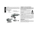
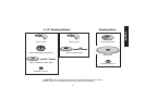
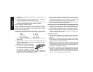
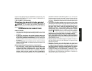
COMPONENTS
A. Switch E. Spindle Lock Pin
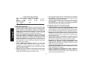
B. Guard F. Unthreaded Backing Flange
C. Wheel G. Threaded Clamp Nut
D. Side Handle
R
ASSEMBLY AND ADJUSTMENTS
CAUTION: Turn off and unplug the tool before making any
adjustments or removing or installing attachments or acces-
sories. Before reconnecting the tool, depress and release the
rear part of the switch to ensure that the tool is off.
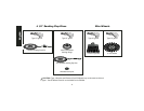
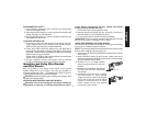
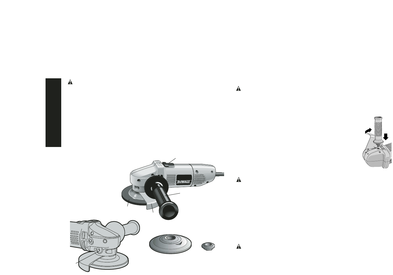
ATTACHING SIDE HANDLE
The side handle can be fitted to either side of the gear
case in the threaded holes, as shown. Before using
the tool, check that the handle is tightened securely.
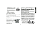
ACCESSORIES
It is important to choose the correct guards, backing
pads and flanges to use with grinder accessories.
See pages 5–6 for information on choosing the cor-
rect accessories. A Type 1 Cut-Off Wheel Guard is
not available for the DW400.
CAUTION: Accessories must be rated for at least the speed
recommended on the tool warning label. Wheels and other acces-
sories running over their rated speed may fly apart and cause
injury. Threaded accessories must have a 5/8" – 11 hub. Every
unthreaded accessory must have a 7/8" arbor hole. If it does not, it
may have been designed for a circular saw. Use only the acces-
sories shown on pages 5–6 of this manual. Accessory ratings must
always be above tool speed as shown on tool nameplate.
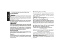
OPERATION
STARTING AND STOPPING THE TOOL
CAUTION: Before connecting the tool to a power supply, be sure
the switch is in the OFF position by pressing the rear part of the
switch and releasing. If the switch is locked on when the power is
connected, the tool will start unexpectedly.
D
C
A
F
G
B
E
English
4