


8
English
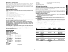
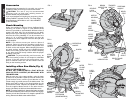
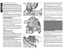
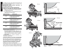
FIG. 11B
STOP SCREW
LOCK NUT
FIG. 12
BEVEL POINTER
SCREW
BEVEL STOP
FIG. 11A
BEVEL
HOUSING
one that best fits your needs. (Page 3)
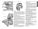
BODY AND HAND POSITION (SEE FIG. 16)
Proper positioning of your body and hands when
operating the miter saw will make cutting easier, more
accurate and safer. Never place hands near cutting area.
Place hands no closer than 6" from the blade. Hold the
workpiece tightly to the table and the fence when cutting.
Keep hands in position until the trigger has been
released and the blade has completely stopped.
ALWAYS MAKE DRY RUNS (UNPOWERED) BEFORE
FINISH CUTS SO THAT YOU CAN CHECK THE PATH
OF THE BLADE. DO NOT CROSS HANDS, AS SHOWN
IN FIGURE 16.
Keep both feet firmly on the floor and maintain proper
balance. As you move the miter arm left and right, follow
it and stand slightly to the side of the saw blade. Sight
through the guard louvers when following a pencil line.
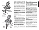
CLAMPING THE WORKPIECE
Turn Off and Unplug Saw
If you cannot secure the workpiece on the table and
against the fence by hand, (irregular shape, etc.) or your
hand would be less than 6” from the blade, a clamp or
other fixture should be used.
For best results us the DW7052 clamp made for use with
your saw. It is available through your local retailer or
D
EWALT service center at extra cost.
Other aids such as spring clamps, bar clamps or C-
clamps may be appropriate for certain sizes and shapes
of material. Use care in selecting and placing these
clamps. Take time to make a dry run before making the
cut. The left fence will slide from side to side to aid in
clamping.
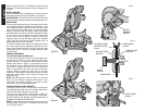
SUPPORT FOR LONG PIECES
Turn Off and Unplug Saw
ALWAYS SUPPORT LONG PIECES
For best results, use the DW7050 extension work
support to extend the table width of your saw. Available
from your dealer at extra cost. Support long workpieces
using any convenient means such as sawhorses or
similar devices to keep the ends from dropping.
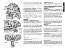
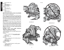
CUTTING PICTURE FRAMES, SHADOW BOXES AND
OTHER FOUR SIDED PROJECTS
To best understand how to make the items listed here,
we suggest that you try a few simple projects using scrap
wood until you develop a “FEEL” for your saw.
Your saw is the perfect tool for mitering corners like the
one shown in Figure 17. Sketch A in Figure 17 shows a
joint made by using the bevel adjustment to bevel the
edges of the two boards at 45 degrees each to produce
a 90 degree corner. For this joint the miter arm was
locked in the zero position and the bevel adjustment was
locked at 45 degrees. The wood was positioned with the
broad flat side against the table and the narrow edge
against the fence. The cut could also be made by
mitering right and left with the broad surface against the
fence.
CUTTING TRIM MOLDING AND OTHER FRAMES
Sketch B in Figure 17 shows a joint made by setting the
miter arm at 45 degrees to miter the two boards to form a
90 degree corner. To make this type of joint, set the
bevel adjustment to zero and the miter arm to 45
degrees. Once again, position the wood with the broad
flat side on the table and the narrow edge against the
fence.
The two sketches in Figure 17 are for four side objects
only.
As the number of sides changes, so do the miter and
bevel angles. The chart below gives the proper angles
for a variety of shapes.
(The chart assumes that all sides are of equal length.)
For a shape that is not shown in the chart, use the
following formula. 180 degrees divided by the number of
sides equals the miter or bevel angle.
- EXAMPLES -
NO. SIDES ANGLE MITER OR BEVEL
445°
536°
630°
7 25.7°
8 22.5°
920°
10 18°
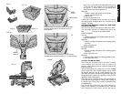
CUTTING COMPOUND MITERS
A compound miter is a cut made using a miter angle and
a bevel angle at the same time. This is the type of cut
used to make frames or boxes with slanting sides like the
one shown in Figure 18.
NOTE: If the cutting angle varies from cut to cut, check
that the bevel clamp knob and the miter lock knob are
securely tightened. These knobs must be tightened after
making any changes in bevel or miter.
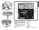
The chart shown on page 13 will assist you in selecting
the proper bevel and miter settings for common
compound miter cuts. To use the chart, select the
desired angle “A” (Figure 19) of your project and locate
that angle on the appropriate arc in the chart. From that
point follow the chart straight down to find the correct
bevel angle and straight across to find the correct miter
angle.
Set your saw to the prescribed angles and make a few
trial cuts. Practice fitting the cut pieces together until you
develop a feel for this procedure and feel comfortable