


2
English
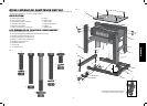
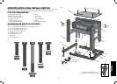
Recommended Tools for Assembly
• 13 mm open end wrench • Cross head screwdriver
• 13 mm socket and ratchet
Assemble the Frame Base and Attach Wheels
1. Slide the short base rails (B) into the long base rails (A) and attach using the four 50 mm hex
bolts (P). Each bolt should be fastened with a lock washer (R) and nut (T). Use 13 mm socket or
wrench to tighten. This will give you the frame base.
2. Attach the 2 wheel brackets (E) to the frame base using 2 carriage bolts (Q), 2 lock washers (R),
and 2 nuts (T).
NOTE: The outside carriage bolt (Q) is used to attach the leg and wheel bracket to the base. It
will need to be left off until the legs are attached.
3. Align the base wheels (D) between the wheel bracket (E) and the long base rails.
4. Place the 60 mm hex bolt (O) through the holes in the bracket, wheel and long base rail until the
threads protrude on the inside of the frame. Fasten the wheels to the base with a lock nut (U)
until the nut is snug and the wheel turns freely.
5. Opposite the wheels, install the rubber leveling feet (F).
Attach the Pivot Wheel Assembly
The pivot wheel assembly (C) for your planer stand can be mounted inboard or outboard of the base.
1. Align the holes on the pivot wheel assembly with the holes on the short base rails of the frame.
2. Position the pivot wheel assembly (C) in the inboard or outboard position.
3. Insert the two 60 mm hex bolts (O) through the holes in the pedal and the rails of the frame.
4. Secure the pedal to the base by tightening the lock washers (R) and nuts (T) with a 13 mm
socket and wrench.
CAUTION: When the pedal is in the outboard position on the stand, keep the mobile planer
stand out of walkways. Tripping and/or other personal injury may result.
Attach the Legs, Support Brackets and MDF Top
1. Place the base frame in the upright position to attach the legs (G) to the corners using 4 carriage
bolts (Q). Tighten the nuts (T) and lock washers (R) with a 13 mm socket or wrench.
2 Attach the short sides (H) to the inside of the legs (G) using 8carriage bolts (Q), 8 lock washers
(R), and 8 nuts (T). Use the socket or wrench to tighten. Be sure the holes in the sides are
aligned with the locating divots provided.
3. Attach the long sides (I) to the inside of the legs (G), overlapping the short sides, using
8carriage bolts (Q), 8 lock washers (R), and 8 nuts (T). Use the socket or wrench to tighten.
Be sure the holes in the sides are aligned with the locating divots provided.
4. Attach the side support brackets (J) to the inside middle of the legs (G) with 4 carriage bolts (Q),
4 lock washers (R) and 4 nuts (T). Use 13 mm socket or wrench to tighten.
5. Attach the MDF top (L) to the sides (I) using the 4 cross head shoulder bolts (M), 4 each of the
lock washers (R) and nuts (T).
Install the Shelf
1. Lay the shelf (K), lip down, on top of the side support brackets.
2. Insert 4 carriage bolts (Q) through the holes in the shelf and the side support brackets.
3. Secure the shelf with lock washers (R) and nuts (T). Use 13 mm socket or wrench to tighten.
Attach the Planer to the Stand (Fig. 1, 3)
WARNING: STABILITY HAZARD. Refer to your tool manufacturer’s instructions regarding the
securing of your planer to a stand or supporting surface. Secure the tool according to both the
instructions in this manual and those in your tool manufacturer’s manual before operating. Failure to
heed these warnings may result in serious personal injury and serious damage to the tool.
Defi nitions: Safety Guidelines
The definitions below describe the level of severity for each signal word. Please read the manual
and pay attention to these symbols.
DANGER: Indicates an imminently hazardous situation which, if not avoided, will result in
death or serious injury.
WARNING: Indicates a potentially hazardous situation which, if not avoided, could result in
death or serious injury.
CAUTION: Indicates a potentially hazardous situation which, if not avoided, may result in
minor or moderate injury.
NOTICE: Indicates a practice not related to personal injury which, if not avoided, may
result in property damage.
IF YOU HAVE ANY QUESTIONS OR COMMENTS ABOUT THIS OR ANY DEWALT TOOL, CALL US
TOLL FREE AT: 1-800-4-D
EWALT (1-800-433-9258).
WARNING: To reduce the risk of injury, read the instruction manual.
Safety Rules and Warnings for Mobile Planer Stand
WARNING: Failure to follow these rules may result in serious personal injury.
• This product was designed to be used as a stand for planers. The stand will support up to
300 lbs (136 kg). Any misuse or abuse can result in product damage or personal injury.
• Do not stand on the work table. It is unsafe to climb, sit or stand on the stand. Do not use the
support extensions as a ladder or scaffolding.
• Properly secure the planer to the stand before operation. Follow the mounting instructions
carefully. Fasten the tool to the MDF top securely as instructed.
• Place the stand on a flat and level surface to prevent rocking or tipping.
• Make sure the planer stand is firmly on the floor, the foot pedal is down and the wheel
is raised before use.
• Do not modify or use the stand for any operation for which it is not intended.
• ALWAYS use eye protection. All users and bystanders must wear eye protection that conforms
to ANSI Z87.1.
• ALWAYS use safety glasses. Everyday eyeglasses are NOT safety glasses. Also use face or dust
mask if cutting operation is dusty. ALWAYS WEAR CERTIFIED SAFETY EQUIPMENT:
• ANSI Z87.1 eye protection (CAN/CSA Z94.3),
• ANSI S12.6 (S3.19) hearing protection,
• NIOSH/OSHA/MSHA respiratory protection.
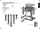
COMPONENTS (FIG. 1, 2)
WARNING: Never modify the stand or any part of it. Damage or personal injury could result.
Refer to Page 1 for a Components List.
ASSEMBLY AND ADJUSTMENTS (FIG. 1, 2)
WARNING: For your own safety, read the tool instruction manual before using any accessory.
Failure to heed these warnings may result in personal injury and serious damage to the planer and
the accessory. When servicing this tool, use only identical replace ment parts.