


English
4
• The label on your tool may include the following symbols. The
symbols and their definitions are as follows:
V..........volts A ..........amperes
Hz ............hertz W ..........watts
min ..........minutes ..........alternating current
........direct current
n
o ..........no load speed
..............
Class II Construction ..........safety alert symbol
..............
earthing terminal
.../min ....revolutions per
.............. ..............minute
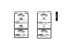
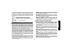
INTRODUCTION
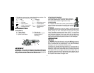
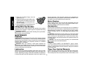
COMPONENTS
A. Trigger Switch D. Side Handle
B. Lock-On Button E. Guard (Type 27, open
C. Spindle Lock Button beneath wheel or
accessory)
ASSEMBLY
CAUTION: Turn off and unplug the tool before making any
adjustments or removing or installing attachments or acces-
sories. Before reconnecting the tool, depress and release the
rear part of the switch to ensure that the tool is off.
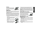
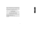
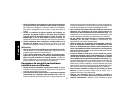
ATTACHING SIDE HANDLE
The side handle can be fitted to either side of the gear
case in the threaded holes, as shown. Before using the
tool, check that the handle is tightened securely.
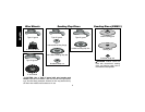
ACCESSORIES
It is important to choose the correct guards, backing
pads and flanges to use with grinder accessories. See
pages 5–6 for information on choosing the correct
accessories.
CAUTION: Accessories must be rated for at least the speed
recommended on the tool warning label. Wheels and other acces-
sories running over their rated speed may fly apart and cause
injury. Threaded accessories must have a 5/8" – 11 hub. Every
unthreaded accessory must have a 7/8" arbor hole. If it does not, it
may have been designed for a circular saw. Use only the acces-
sories shown on pages 5–6 of this manual. Accessory ratings must
always be above listed tool speed as shown on tool nameplate.
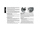
OPERATION
Switch
CAUTION: Check that the tool is not locked ON before connect-
ing it to a power supply. If the trigger switch is locked ON when the
tool is connected to the power supply, it will start immediately.
Damage to your tool or personal injury may result.
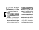
To start the tool, squeeze the trigger switch (A). To turn the tool off,
release the switch. The tool can be locked on for continuous use by
holding the trigger switch depressed while you depress the switch
locking button next to the trigger. Hold the lock-on button (B) in as
you gently release the trigger. Release the locking button and the
tool will continue to run. To turn the tool off from a locked on condi-
tion, squeeze and release the trigger once.
A
B
C
D
E