


accessoriesrunningoverratedspeedcanflyapartandcauseinjury.
Accessoryratingsmustalwaysbeabovetoolspeedasshownon
toolnameplate.
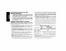
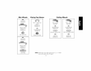
A'n'AC HMENTS
Attachments designed specifically for this grinder can be
purchased through DEWALT dealers and DEWALT Factory Service
centers.
9" Type 27 guard
9" Type 28 guard
7" Type 27 guard
6" Type 11 Flaring cup guard with flange
4" Type 11 Flaring cup guard with flange
Type 11 Flaring cup wheel backing flange
Type 1 Flange set
7" Type 1 Guard
Grinding backing flange
Clamp nut
Wheel Wrench
Soft mount spindle protector
ASSEMBLY AND ADJUSTMENTS
D284939
D284938
D284937
D284936
D284934
608368-00
D284932
D284931
54339-00
22191-00
61820-01
445928-01
A WARNING: To reduce the risk of injury, turn unit off
and disconnect it from power source before installing and
removing accessories, before adjusting or when making
repairs. An accidental start-up can cause injury.
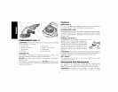
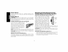
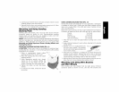
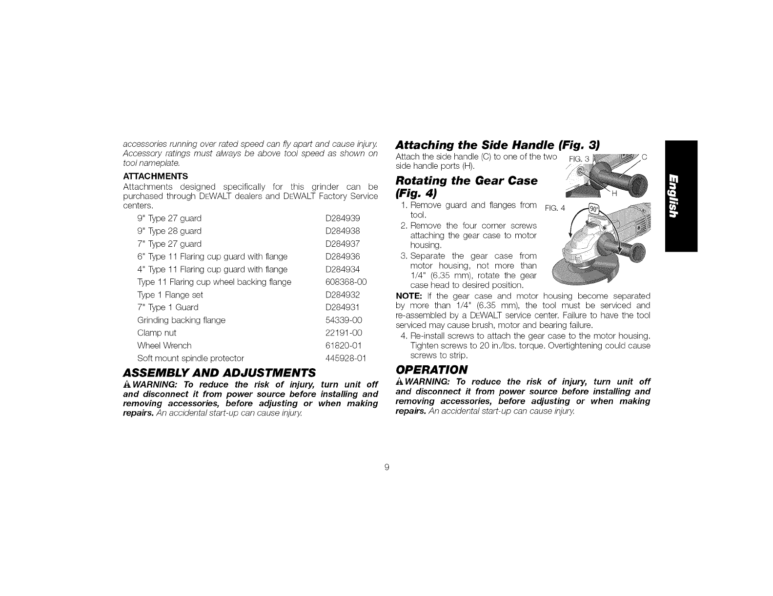
Attaching the Side Handle (Fig. 3)
Attach the side handle (C) to one of the two FIG.3
side handle ports (H). /
Rotating the Gear Case
(Fig. 4)
1. Remove guard and flanges from FIG.4
tool.
2. Remove the four corner screws
attaching the gear case to motor
housing.
3. Separate the gear case from
motor housing, not more than
1/4" (6.35 mm), rotate the gear
case head to desired position.
NOTE: If the gear case and motor housing become separated
by more than 1/4" (6.35 mm), the tool must be serviced and
re-assembled by a DEWALT service center. Failure to have the tool
serviced may cause brush, motor and bearing failure.
4. Re-install screws to attach the gear case to the motor housing.
Tighten screws to 20 in./Ibs, torque. Overtightening could cause
screws to strip.
OPERATION
A WARNING: To reduce the risk of injury, turn unit off
and disconnect it from power source before installing and
removing accessories, before adjusting or when making
repairs. An accidental start-up can cause injury.