


The following table is intended as a general guide only. Determine the type of material and
dimension of the workpiece and select the most appropriate band saw blade.
CAUTION: Never use the band saw to cut resin materials which are subject to melting. Melting
of resin material caused by high heat generated during cutting may cause the band saw blade
to become bound to the material, possibly resulting in overload and burn-out of the motor.
BLADE DESCRIPTION
Type of band saw blade Bi-Metal
Number of teeth
24 18 14 10 14/18 10/14
Workpiece thickness
1/8" (3.2 mm) and under • •
1/8" - 1/4" (3.2 mm - 6.4 mm) • •
1/4" - 13/32" (6.4 mm - 10.3 mm) • •
13/32" (10.3 mm) and over •
Blade Speed
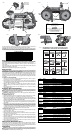
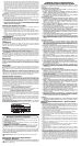
Your DWM120 portable band saw is equipped with variable speed for greater versatility.
Turn the speed wheel (I) to select the desired speed (Fig. 1). Speed 1 is the slowest speed;
Speed 5 is the fastest. Use speed settings 1–5 when connected to an AC power supply.
When cutting copper, brass, bronze, aluminum, cast iron, angle iron, and mild steel, use a
higher speed.
When cutting plastic pipe, tougher steels, chrome steel, tungsten steel, stainless steel, and
other problem materials, use low speed.
NOTE: When cutting plastic pipe, higher speeds may melt plastic.
Blade Tracking
WARNING: To reduce the risk of serious personal injury, turn tool off and disconnect
tool from power source before making any adjustments or removing/installing attachments
or accessories. An accidental start-up can cause injury.
Your band saw is equipped with an adjustable blade tracking mechanism which assures
proper blade tracking at all times. The back edge of a properly aligned blade will run
lightly against one or both of the back up rollers in the blade guides. (The pressure between
the edge of the blade and the roller will be very slight and will not damage either the blade
or the roller.)
TO ADJUST THE BLADE TRACKING
1. Use a 1/2" (13 mm) wrench to loosen the adjustment locking nut (G), shown in Figure 1
by turning it one or two turns counterclockwise.
2. Use a screwdriver to turn the tracking screw 1/4 turn. Turning the screw clockwise will
move the blade up toward the blade guide rollers. Turning the screw counterclockwise will
move the blade down away from the rollers.
3. Adjust so that the back edge of the blade lightly touches the rollers then securely
tighten the locking nut. (It will be necessary to plug the saw in and run it to observe the
tracking.)
4. Observe blade tracking between runs and repeat Steps 1–4 as necessary to achieve
proper blade tracking.
Removing and Installing Blades
WARNING: To reduce the risk of serious personal injury, turn tool off and disconnect
tool from power source before making any adjustments or removing/installing attachments
or accessories. An accidental start-up can cause injury.
CAUTION: Cut Hazard. Blade tension lever is under spring pressure. Maintain control of
lever when releasing blade tension.
TO REMOVE BLADE (FIG. 1, 2)
1. Rotate the blade tension lever (H) clockwise until it stops to release tension in blade.
2. Turn the saw over and place it on a workbench or table with the cord to the left.
3. Begin removing the blade at the blade guard (M) and continue around the pulleys (L).
When removing the blade, tension may be released and the blade may spring free. SAW
BLADES ARE SHARP. USE CARE IN HANDLING THEM.
4. Inspect the guide rollers (F1, F2) and remove any large chips which may be lodged in
them. Lodged chips can prevent rotation of the guide rollers and cause flat spots on the
guide rollers.
5. Rubber tires (N) are mounted on the pulleys (L). The rubber tires should be inspected
for looseness or damage when changing the blade. Wipe any chips from the rubber tires
on the pulleys. This will extend tire life and keep the blade from slipping. If any looseness
or damage occurs, the tool should be brought to an authorized D
EWALT service center
for repair or replacement as soon as possible. Continued use of the tool with loose or
damaged rubber tires will cause unstable travel of the band saw blade.
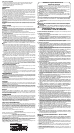
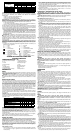
TO INSTALL BLADE (FIG. 1, 3–5)
1. Position the blade so that the teeth are on the bottom and angled toward the work stop,
as shown in Figures 1 and 3.
2. Slip the blade into the guide rollers, as shown in Figure 4.
3. Holding the blade in the guide rollers, place it around both pulleys (L) and through the
work stop (E), as shown in Figure 5.
4. Make sure that the blade is fully inserted into the guide rollers and positioned squarely
against the rubber tires.
5. Rotate the blade tension lever (H) counterclockwise until it stops and then gently turn the
saw over so that the pulleys rest on your work bench or table and. Make sure the teeth
face away from the bandsaw (Fig. 1, 3).
6. Turn the speed wheel to low speed (1) and then turn the saw on and off a few times to
ensure that the blade is seated properly.
Multi-position Bail Handle (Fig. 1)
A bail handle is provided for carrying the tool and for use as an additional handle. Assemble
the bail handle in one of the milti-positions (forward, 45º or straight up) shown in Figure 1.
When adjusting the bail handle from one position to the other, loosen the bail handle knob and
move the handle to one of the three positions and tighten knob.
Adjustments
WARNING: To reduce the risk of serious personal injury, turn tool off and disconnect
tool from power source before making any adjustments or removing/installing attachments
or accessories. An accidental start-up can cause injury.
FIG 4
FIG. 5
E
YES / OUI / SÍ
NO / NON / NO
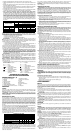
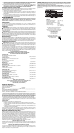
FIG. 7
RECOMMENDED CUTTING POSITIONS / POSITIONS DE COUPE
RECOMMANDÉES / POSICIONES DE CORTE RECOMENDADAS
FIG. 6
YES / OUI / SÍ
YES / OUI / SÍYES / OUI / SÍ
YES / OUI / SÍ
YES / OUI / SÍ
NO / NON / NO
NO / NON / NO
NO / NON / NO
NO / NON / NO
NO / NON / NO
Item Model DWM120
Motor
Type Protected type, series commutator motor
Power source single-phase, AC 60Hz
Voltage 120 volts
Full-load current 10 amp
Band Saw
Blade
Dimensions 1/2" x 44-7/8" x .020"
(12.5 mm x 1140 mm x .5 mm)
Peripheral speed 100 - 350 ft/min (30 - 106 m/min)
Max. Cutting
Dimensions
Pipe outer dimensions 4-3/4" (120.7 mm)
Stock 5" x 4-3/4" (127 mm x 120.7 mm)
Net Weight
15 lbs. (6.8 kg)
Cord
3 conductor type captive cable 8.0 ft. (2.4 m)
L
J
A
D
L
E
K
FIG. 2
M
N
FIG. 1
A
B
D
E
F1
I
H
C
J
O
P
R
LOOSEN
DESSERRER
AFLOJE
F2
G
BLADE DIRECTION
DIRECTION DE LA LAME
DIRECCIÓN DE LA HOJA
STRAIGHT UP
TOUT DROIT
HACIA ARRIBA
45º
FIG. 3
BLADE DIRECTION
DIRECTION DE LA LAME
DIRECCIÓN DE LA HOJA
POSITION OF TEETH ON LEFT SIDE OF MACHINE
POSITION DES DENTS SUR LE CÔTÉ
GAUCHE DE LA MACHINE
POSICIÓN DE LOS DIENTES EN EL LADO
IZQUIERDO DE LA MAQUINA
Article Modèle DWM120
Moteur
Type Type protégé, série moteur à collecteur
Source de courant monophasé, CA 60Hz
Tension 120 volts
Courant de pleine
charge
10 amp
Lame de
scie à ruban
Dimensions 12,5 mm x 1140 mm x 0,5 mm
(1/2 po x 44-7/8 po x 0,020 po)
Vitesse périphérique 30 - 106 m/min (100 - 350 pi/min)
Longueurs
max. de
coupe
Dimensions externes
de tuyau
120.7 mm (4-3/4 po)
Bois spéciaux 127 mm x 120.7 mm (5 po x 4-3/4 po)
Poids net
6,8 kg (15 lb)
Cordon
Cordon à 3 broches et 3 conducteurs
de 2,4 m (8 pi)
Artículo Modelo DWM120
Motor
Tipo Tipo protegido, serie de motor commutador
Alimentación Eléctrica Corriente alterna de 60Hz, monofásica
Voltaje 120 voltios
Corriente a carga
completa
10 amperios
Hoja de la
Sierra de
Banda
Dimensiones 12.5 mm x 1140 mm x .5 mm
(1/2 pulg. x 44-7/8 pulg. x .020 pulg.)
Velocidad periférica 30 - 106 m/min (100 - 350 pie/min)
Máx.
Dimensiones
de Corte
Dimensiones externas
de tubería
120.7 mm (4-3/4 pulg.)
Reserva 127 mm x 120.7 mm (5 pulg. x 4-3/4 pulg.)
Peso Neto
6,8 kg (15 lbs)
Cable
3 Cables tipo cautivos conductores
de 2,4 m (8,0 pie)