


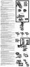
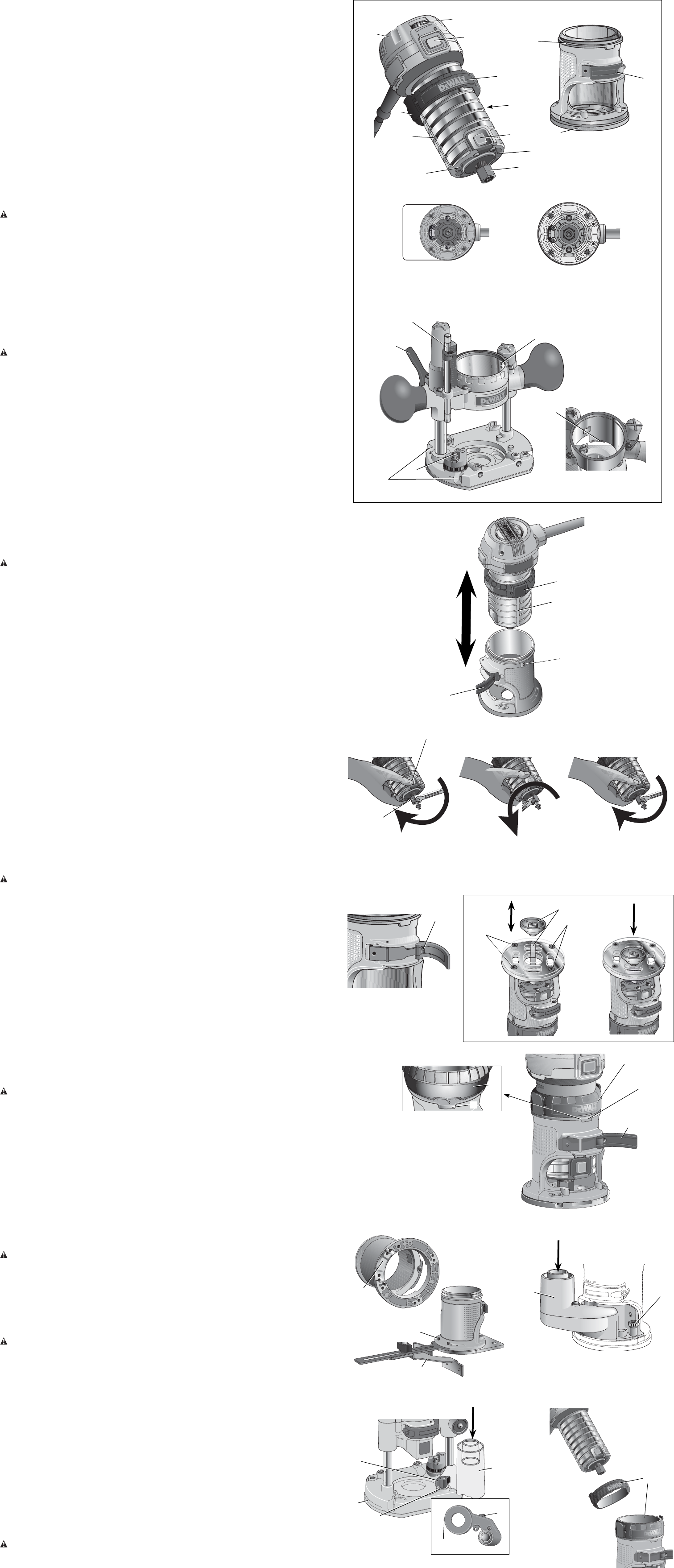
c. Depress the spindle lock button (E) again and turn the wrench clockwise.
d. Repeat the procedure until the collet nut (U) reaches desired tightness.
NOTICE: Avoid possible damage to the collet. Never tighten the collet without a bit.
TO REMOVE THE BIT
1. Remove the motor unit from the base unit, see Motor Quick Release.
2. Depress the spindle lock button (E) to hold the spindle shaft in place while turning the collet
nut (U) counterclockwise with the wrench provided.
To loosen using the "manual ratchet" method:
a. Without removing the wrench from the collet nut (U), release pressure on the spindle lock
button (E).
b. With the wrench still on the collet nut (U), reverse the loosening direction to reset the
wrench position.
c. Depress the spindle lock button (E) again and turn the wrench counterclockwise.
d. Repeat the procedure until the collet nut (U) is loose and the bit can be removed.
Collets
NOTE: Never tighten the collet without first installing a router bit in it. Tightening an empty
collet, even by hand, can damage the collet.
To change collet sizes, unscrew the collet assembly as described above. Install the desired
collet by reversing the procedure. The collet and the collet nut are connected. Do not attempt
to remove the collet from the collet nut.
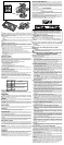
Locking Lever Adjustment (Fig. 4)
WARNING: To reduce the risk of injury, turn unit off and disconnect it from power
source before installing and removing accessories, before adjusting or when making
repairs. An accidental start-up can cause injury.
Excessive force should not be used to clamp the locking lever. Using excessive force may
damage the base.
When the locking lever is clamped the motor should not move in the base.
Adjustment is needed if the locking lever will not clamp without excessive force or if the motor
moves in the base after clamping.
To adjust the locking lever’s clamping force:
1. Open the locking lever (I).
2. Using a hex wrench turn locking lever adjustment screw (S) in small increments.
Turning the screw clockwise tightens the lever, while turning the screw counterclockwise
loosens the lever.
Centering the Subbase (Fig. 5)
WARNING: To reduce the risk of injury, turn unit off and disconnect it from power
source before installing and removing accessories, before adjusting or when making
repairs. An accidental start-up can cause injury.
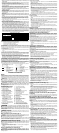
If you need to adjust, change, or replace the subbase, a centering tool is recommended, refer
to Accessories. The centering tool consists of a cone and a pin.
To adjust the subbase, follow the steps below.
1. Loosen but do not remove the subbase screws (FF) so the subbase moves freely.
2. Insert the pin into the collet and tighten the collet nut.
3. Insert the motor into the base and clamp the locking lever on the base.
4. Place the cone on the pin (Fig. 5A) and lightly press down on the cone until it stops as
shown in Figure 5B. This will center the subbase.
5. While holding down on the cone, tighten the subbase screws.
Using Template Guides
The round subbase will accept universal template guides. Recommended accessories for use
with your tool are available at extra cost from your local dealer or authorized service center.
NOTE: The D-shape subbase does not accommodate template guides and is designed to
accommodate bits up to 1-3/8" (34.9mm) in diameter.
To use Template Guides:
1. Center the subbase. See Centering The Subbase.
2. Install template guide (available as an accessory) on the subbase and tighten securely.
Adjusting the Depth of Cut (Fig. 6)
WARNING: To reduce the risk of injury, turn unit off and disconnect it from power
source before installing and removing accessories, before adjusting or when making
repairs. An accidental start-up can cause injury
1. Select and install the desired bit. See Bit Installation and Removal.
2. Assemble base to motor, ensuring base is attached to the depth adjustment ring. Place
router on the work piece.
3. Open the locking lever (I) and turn the depth adjustment ring (B) until the bit just touches
the work piece. Turning the ring clockwise raises the cutting head while turning it
counterclockwise lowers the cutting head.
4. Turn the micro adjustable scale (H) clockwise until the 0 on the scale lines up with the
pointer on the bottom of the depth adjustment ring.
5. Turn the depth adjustment ring until the pointer lines up with desired depth of cut marking
on the micro adjustable scale.
NOTE: Each mark on the adjustable scale represents a depth change of 1/64" or .015" (0.4
mm) and one full (360º) turn of the ring changes the depth 0.5" (12.7mm).
6. Close the locking lever (I) to lock the base.
Using an Edge Guide (Fig. 7, 9)
An edge guide (model DNP618) is available from your local retailer or service center at extra
cost.
1. Remove the motor unit from the base unit, see Motor Quick Release.
2. Remove flat head screws (GG) from storage holes on edge guide.
3. Slide edge guide into edge guide slot (J) on side of fixed base or (X) on side of the plunge
base. Insert the two flat head screws through the appropriate holes in the sub base to
secure the edge guide. Tighten hardware.
4. Follow all instructions included with the edge guide.
NOTE: To remove the edge guide, reverse the above procedure. After removing edge guide
always replace the two flat head screws into the storage holes on the edge guide to prevent
loss.
Using a Premium Edge Guide (Plunge Base Only)
A Premium Edge Guide (model DW6913) is available from your local retailer or service center at
extra cost. Follow the assembly instructions included with the edge guide.
Vacuum Attachment (Fixed Base Only, Fig. 8)
WARNING: To reduce the risk of injury, turn unit off and disconnect it from power
source before installing and removing accessories, before adjusting or when making
repairs. An accidental start-up can cause injury.
To connect the router to a vacuum cleaner for dust collection, follow these steps:
1. Remove the motor unit from the base unit, see Motor Quick Release.
2. Attach vacuum attachment accessory (V) to the base as shown. Tighten thumb screws (W)
securely by hand.
3. Attach hose adapter to vacuum attachment accessory.
4. When using vacuum attachment, be aware of the placement of the vacuum cleaner. Be sure
that the vacuum cleaner is stable and that its hose will not interfere with the work.
Vacuum Attachment (Plunge Base Only, Fig. 9)
1. Remove the motor unit from the plunge base, see Motor Quick Release.
2. Slide tab (HH, inset) on vacuum attachment into slot in plunge base and snap tab (II, inset)
into hole in plunge base.
3. Secure to base with supplied plastic washer (JJ) and thumb screw (KK). Tighten thumb
screw securely by hand.
4 Attach hose adaptor to vacuum attachment.
5. When using vacuum attachment, be aware of the placement of the vacuum cleaner. Be sure
the vacuum cleaner is stable and its hose will not interfere with the work.
Set-up: Fixed Base (Fig. 1, 2)
INSERTING THE MOTOR INTO THE FIXED BASE (FIG. 1, 2, 10)
WARNING: To reduce the risk of injury, turn unit off and disconnect it from power
source before installing and removing accessories, before adjusting or when making
repairs. An accidental start-up can cause injury
1. Open the locking lever (I) on the base.
2. If the depth adjustment ring (B) is not on the motor, thread the depth adjustment ring (B)
onto the motor until the ring is about halfway between the top and bottom of the motor
as shown. Insert the motor into the base by aligning the groove on the motor (G) with the
guide pins (R) on the base. Slide the motor down until the depth adjustment ring snaps into
place.
NOTE: Guide pin grooves (G) are located on either side of the motor so it can be positioned
in two orientations.
3. Adjust the depth of cut by turning the depth adjustment ring. See Adjusting the Depth of
Cut.
4. Close the locking lever (I) when the desired depth is achieved. For information on setting
the cutting depth, see Adjusting the Depth of Cut.
Set-up: Plunge Base (Fig. 1, 10, 11)
INSERTING THE MOTOR INTO THE PLUNGE BASE
WARNING: To reduce the risk of injury, turn unit off and disconnect it from power
source before installing and removing accessories, before adjusting or when making
repairs. An accidental start-up can cause injury
1. Remove the depth adjustment ring (B) from the motor. It is not used with the plunge base.
NOTE: Snap depth adjustment ring onto fixed base, when not in use, to prevent loss.
2. Insert the motor into the base by aligning the groove on the motor (G) with the guide pins
(R) on the base. Slide the motor down until the motor stops on the motor stop (AA).
3. Close the locking lever (I).
ADJUSTING THE PLUNGE ROUTING DEPTH (FIG. 11)
WARNING: To reduce the risk of injury, turn unit off and disconnect it from power
source before installing and removing accessories, before adjusting or when making
repairs. An accidental start-up can cause injury
1. Unlock the plunge mechanism by pulling down the plunge lock lever (P). Plunge the router
down as far as it will go, allowing the bit to just touch the workpiece.
2. Lock the plunge mechanism by releasing the plunge lock lever (P).
3. Loosen the depth adjustment rod (O) by turning the thumb screw (BB) counterclockwise.
4. Slide the depth adjustment rod (O) down so that it meets the lowest turret stop (N).
5. Slide the zero adjuster tab (EE) on the depth adjustment rod down so that the top of it meets
zero on the depth adjustment scale (DD).
6. Grasping the top, knurled section of the depth adjustment rod (O), slide it up so that the tab
(EE) aligns with the desired depth of cut on the depth adjustment scale (DD).
7. Tighten the thumb screw (BB) to hold the depth adjustment rod in place.
8. Keeping both hands on the handles, unlock the plunge mechanism by pulling the plunge
lock lever (P) down. The plunge mechanism and the motor will move up. When the router
is plunged, the depth adjustment rod will hit the turret stop, allowing the router to reach
exactly the desired depth.
USING THE ROTATING TURRET FOR STEPPED CUTS (FIG. 11)
If the depth of cut required is more than is acceptable in a single pass, rotate the turret so that
depth rod (O) lines up with taller turret stop initially. After each cut, rotate the turret so that the
depth stop lines up with shorter post until the final depth of cut is reached.
WARNING: Do not change the turret stop while the router is running. This will place your
hands too near the cutter head.
MOTOR - BLOC
MOTEUR - UNIDAD
DEL MOTOR
FIG. 1
S
FIG. 4
FIG. 8
FIXED BASE - BASE FIXE - BASE FIJA
I
K
H
ROUND SUBBASE
SEMELLE RONDE
SUB-BASE REDONDA
D-SHAPED SUBBASE
SEMELLE EN D
SUB-BASE EN FORMA DE D
M
N
O
P
PLUNGE BASE
BASE PLONGEANTE
BASE PARA PENETRACIÓN
AA
A
E
D
F
C
B
G
U
FIG. 2
A
R
G
I
FIG. 3
E
U
FIG. 7
Q
J
GG
FIG. 5B
Z
FIG. 6
I
B
H
B
H
FIG. 5A
FF
FF
T
TIGHTEN
SERRER
APRETAR
RESET
RÉINITIALISER
REPOSICIONAR
TIGHTEN
SERRER
APRETAR
V
W
FIG. 9
HH
II
KK
JJ
L
R
FIG. 10
B
F
X
G