28
13 1415
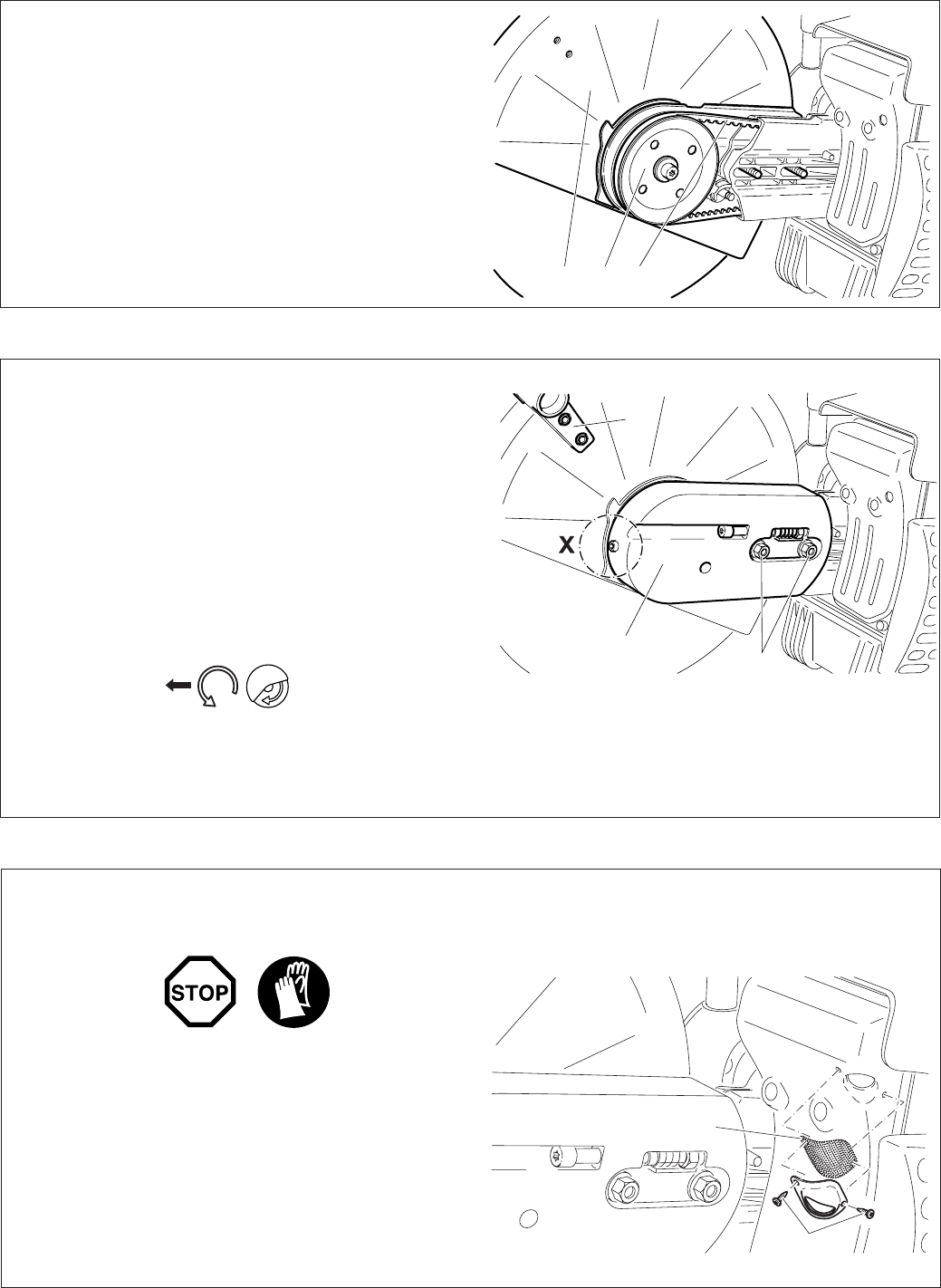
Press the cutting attachment (13) onto the drive arm in the
side position.
Guide the V-belt (14) over the V-belt pulley (15).
NOTE: The illustration shows the V-belt for models PC-6430
- 7335).
Put the guard plate (16) on.
Screw on nuts (17) and tighten by hand.
To tighten the V-belt see ”Tightening the V-belt / Checking V-
belt tension”.
Screw in and tighten the screw (detail X, only for PC-8140).
Tighten the nuts (17) rmly with the combination wrench.
Replace the grip (18) as shown.
IMPORTANT:
When you reposition the cutting attachment, the direction
of rotation of the cutting wheel changes.
If a rotation direction is marked on the cutting disc, make
sure the disc turns in the right direction.
16
17
18
19
20
Replacing/cleaning the spark arrester screen
The spark arrester screen should be checked and cleaned
regularly.
Loosen the 2 screws (19) and remove the spark arrester
screen (20).
Reassembly the spark arrester screen and tighten the screws.
CAUTION:
Do not use sharp or pointed objects for screen cleaning.
Damaged or misformed screen wires may result.


