


Disassembly/Assembly Instructions
Important: Manufacturer’s warranty is void if tool is disassembled before warranty expires.
Warning: The governor in this tool is preset at the factory to maintain the maximum rated speed for the tool, any repairs to this assembly should be
done at the Dynabrade factory. A Motor Tune-Up Kit is available (P/N 96047) to help maintain motor in peek operating condition.
To Disassemble:
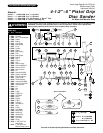
1. Remove disc mount assembly or Roloc
®
Pad and 53163 Side Handle.
2. Place machine housing in soft jaw vise. Important: Be careful not to over tighten vise to prevent damage.
3. Turn 55029 Cover clockwise (left hand threads) and remove.
4. Pull motor assembly from housing.
5. Remove 56028 Muffler Cap. Use a 12 mm hex key to unscrew 57066 Muffler Body and 57075 Cone Muffler from housing.
6. Unscrew 56023 Inlet Bushing and remove.
Motor Disassembly:
1. Secure motor in a vise using flats on 55034 or 55038 Adapter.
2. Screw governor assembly clockwise (left hand threads) to remove from rear of motor.
Note: Any shims between the governor and back of rotor must be kept and replaced during assembly.
3. Press rotor from 02649 Bearing and 01743 Bearing Plate.
4. Press 02649 Bearing from 01743 Bearing Plate.
5 Remove 01028 Cylinder and 01185 Blades (4) from rotor.
6. Secure 55025 Rotor in soft jaw vise.
7 Unscrew 55034 or 55038 Adapter and remove from rotor.
8. Remove 01007 Front Bearing, 55026 Bearing Plate and 01010 Spacer from rotor.
9. Remove 01007 Bearing and any shims from 55026 Bearing Plate.
Valve Disassembly:
1. Drive 96025 Pin through housing and remove valve assembly from housing.
2. Remove 96025 Pin from housing.
3. Remove trigger/valve assembly from housing.
4. Remove first 55051 Valve Stop (Press valve stem from valve stop, be careful not to damage 55041 Valve. A small bearing puller is recommended).
5. Remove 55041 Valve and separate.
6. Press 55042 Valve Stem through the second 55051 Valve Stop.
Motor Assembly:
Important: Be certain all parts are cleaned, properly greased and in good repair before assembling.
1. Install 01007 Front Bearing into 55026 Bearing Plate. (Note: Shimming may be required in upcoming steps).
2. Install 01010 Spacer on rotor.
3. Install bearing assembly onto rotor and spacer.
4. Secure 55025 Rotor in padded vise.
5. Screw 55034 or 55038 Adapter onto 55025 Rotor, torque to 17 N•m/150 in. - lbs.
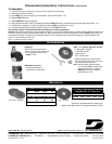
6. Use a .001" thick feeler gauge to set clearance between the 55026 Bearing Plate and 55025 Rotor.
Note: If shimming is required, use the 01121 Shim Pack accordingly to shim between the 01007 Bearing and 55026 Bearing Plate to obtain a .001"
clearance between the bearing plate and rotor.
7. Install 01185 Blades (4) onto 55025 Rotor. (Note: Blades should be lubricated with Dynabrade Air Lube P/N 95842 or equivalent before installation).
8. Install 01028 Cylinder over 55025 Rotor and onto 55026 Bearing Plate. Be sure to line up 50767 Pin in 55026 Bearing Plate with hole in 01028 Cylinder
Note: Air inlet holes in cylinder should face away from 55026 Bearing Plate.
9. Press 02649 Bearing into 01743 Bearing Plate.
10. Press bearing and bearing plate onto rotor. Be sure 50767 Pin in 01743 Bearing Plate lines up with hole in 01028 Cylinder.
Important: The fit must be snug between bearing plates and cylinder. If to tight, rotor will not turn freely. Rotor must then be lightly tapped at short end
so it will turn freely while still maintaining a snug fit. A loose fit will not achieve the proper pre-load of the motor bearings.
11. Place motor in vise using flats on 55034 or 55038 Adapter.
12. Replace any shims that were between back of rotor and governor, then screw governor assembly counter-clockwise and torque to 10 N•/90 in. - lbs.
Valve Assembly:
1. Slide 55039 Bushing (with o-rings) onto valve stem/trigger assembly.
2. Press 55051 Valve Stop onto 55052 Valve Stem large end out.
3. Install 55041 Valve onto valve stem.
4. Install 96147 O-Ring onto the 55051 Valve Stop.
5. Press 55051 Valve Stop onto valve stem with o-ringed end facing valve. Press valve stop until flush with valve stem end.
6. Reinsert into housing and replace 96025 Pin.
(continued on next page)
3