


3
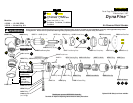
Disassembly/Assembly Instructions - DynaFine
TM
Important: Manufacturer’s warranty is void if tool is disassembled before warranty expires
Notice: Dynabrade strongly recommends the use of their 52296 Repair Collar (sold separately) during assembly/disassembly activities. Failure to
use this collar will highly increase the risk of damage to the valve body of this tool. Please refer to parts breakdown for part identification.
Motor Disassembly:
1. Disconnect tool from power source.
2. Secure air tool in vise using 52296 Repair Collar.
3. Remove sanding pad assembly.
4. Loosening 95884 Hose clamp.
5. Remove bearing/boot assembly.
6. With an adjustable pin wrench, remove 01560 Exhaust Cover by turning counter-clockwise.
7. Pull motor assembly from housing.
8. Remove 57961 Cam Assembly from rotor shaft.
9. Remove 53161 Front Bearing Plate, cylinder, and blades (4) from rotor. Note: The 40544 Bearing and 53161 Front Bearing Plate are a slip fit onto rotor.
10. Press rotor from 02673 Rear Bearing Plate. Remove 02679 Shield. Press 02696 Bearing from rear bearing plate.
Motor disassembly is complete.
Valve Body Disassembly:
1. Reposition motor housing in vise so inlet bushing is facing upwards.
2. Remove 94523 Inlet Bushing and muffler assembly from valve body housing. Using needle nose pliers, remove 01468 Spring, tip valve and seal.
3. Remove 95711 Retaining Ring from inlet adapter and disassemble muffler assembly.
4. Using a 2.5mm diameter drift pin and a hammer, tap 12132 Pin out from housing and remove throttle lever.
5. Remove 95558 Retaining Ring and push 01469 Speed Regulator from housing.
Tool disassembly is complete.
Motor Reassembly:
Important: Be sure parts are clean and in good repair before reassembly.
1. Place 50777 Rotor in padded vise with threaded spindle facing upwards.
2. Install bearing/bearing plate assembly onto rotor.
3. Tighten 57961 Cam Assembly onto rotor (torque to 17 N•m/150 in. - lbs.).
4. Install well lubricated 01480 Blades (4) into rotor slots. Dynabrade Air Lube P/N 95842 is recommended for lubrication.
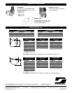
5. Install cylinder over rotor. Be sure air inlet holes of cylinder face away from bearing plate and that the pin in the front bearing plate aligns correctly
with the pin-hole in the cylinder.
6. Install 02696 Rear Bearing into 02673 Rear Bearing Plate. Press bearing/bearing plate assembly onto rotor. Be sure that pin and air inlet holes line-up
with pin slot and air inlet holes in cylinder. Install 02679 Shield.
Important: Fit must be snug between bearing plates and cylinder. A loose fit will not achieve the proper preload of motor bearings. If too tight, rotor will not
turn freely. Rotor must then be lightly tapped at press fit end so it will turn freely while still maintaining a snug fit.
7. Secure housing in vise using 52296 Repair Collar.
8. Install motor assembly into housing. Be sure motor drops all the way into housing.
9. Install 01560 Exhaust Cover onto motor housing (torque 28 N•m/250 in. - lbs.).
10. Install boot assembly onto tool. Tighten 95884 Hose clamp.
Motor assembly is complete.
Valve Body Reassembly:
1. Insert 01469 Speed Regulator Assembly with 01449 Valve Stem with o-rings installed into housing. Secure with 95558 Retaining Ring.
2. Secure valve body in vise using 52296 Repair Collar with air inlet facing upwards.
3. Insert 01464 Seal into housing.
4. Line-up the hole in the 01449 Valve Stem with the hole in the housing (looking past brass bushing). Insert 01472 Tip Valve so that the metal pin passes
through the hole in the valve stem. Install 01468 Spring (small end first).
5. Reassemble muffler assembly. Slip 94523 Inlet Adapter through muffler assembly and secure with 95711 Retaining Ring.
6. Install o-ring onto air control ring, install into valve body housing.
7. Apply Hernon #940 PST Pipe Sealant (or equivalent) to threads of inlet bushing and install muffler assembly onto valve body (torque 23.0 N•m/200 in. - lbs.).
8. Install throttle lever and 12132 Pin. Remove from vise.
Tool assembly is complete. Please allow 30 minutes for adhesives to cure before operating tool.
Important: Motor should now be tested for proper operation at 90 PSI. If motor does not operate properly or operates at a higher RPM than marked on the
tool, the tool should be serviced to correct the cause before use. Before operating, place 2-3 drops of Dynabrade Air Lube (P/n 95842) directly into air inlet with
throttle lever depressed. Operate tool for thirty seconds to determine if tool is operating properly and to allow lubricating oils to properly penetrate motor.
Loctite® is a registered trademark of Loctite Corp.