


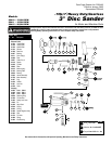

Disassembly/Assembly Instructions – 3" Disc Sander .7 Hp/7˚ Gearless Front Exhaust
Important: The Manufacturer's warranty is void if the tool is disassembled before the warranty expires.
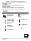
Notice: All of the special repair tools referenced in these instructions can be ordered from Dynabrade. Please refer to this parts page for the
proper part identification.
Motor Disassembly:
1. Disconnect the tool from the air supply.
2. Carefully secure the 01739 Housing in a vise with aluminum or bronze jaws. Hold the back portion of the housing opposite the exhaust cover so as not
to crush the housing.
3. Remove the 50187 3" Dynapad.
4. Use a 1-1/2" open end or an adjustable wrench to remove the exhaust cover by turning it counterclockwise and remove the 01744 Silencer.
5. Pull the air motor out of the 01739 Housing.
6. Remove the 01739 Housing from the vise.
7. Fasten the 96346 Bearing Separator around the portion of the 01028 Cylinder that is closest to the 01743 Bearing Plate.
8. Place the motor with the separator attached on the table of the 96232 Arbor Press and using a 3/16" dia. flat end drive punch as a press tool push the
rear stem of the 55025 Rotor out of the 02649 Bearing.
9. Use the 96213 Bearing Removal tool and the arbor press to remove the 02649 Bearing from the 01743 Bearing Plate.
10. Secure the vane slot portion of the 55025 Rotor in a vise with aluminum or bronze jaws so that the threaded stem of the rotor is pointing up.
11. Use an adjustable wrench to remove the 01708 Rotor Nut from the rotor by turning it counterclockwise.
12. Slip the 01008 Bearing Plate, 01007 Bearing, shims and 01010 Spacer from the rotor.
Motor Disassembly Complete.
Valve Disassembly:
1. Position the valve housing in a vise so that the air inlet is pointing up.
2. Hold the 01494 Inlet Bushing stationary with an adjustable wrench while removing the air fitting.
3. Use a wrench to remove the air inlet bushing from the valve housing.
4. Remove the 01468 Spring, 01472 Tip Valve, and 01464 Seal from the valve housing.
5. Use a 2.5mm drive punch to remove the 12132 Pin and the throttle lever from the valve housing.
6. Remove the 95558 Retaining Ring with retaining ring pliers.
7. Push the 01469 Speed Regulator Assembly out of the housing and remove the 01449 Valve Stem.
Valve Disassembly Complete.
Valve Assembly:
Important: Clean and inspect all of the parts for wear before assembling.
1. Install the 01469 Speed Regulator Assembly (includes o-rings) into the valve housing and secure it in place with the 95558 Retaining Ring.
2. Insert the 01449 Valve Stem so that the hole in the valve stem is visible through the air inlet opening.
3. Install the 01464 Seal into the air inlet opening of the valve housing so that it lays flat.
4. Use a needle to install the 01472 Tip Valve into the air inlet opening so that the metal pin of the tip valve passes through the hole in the valve stem.
5. Place the smaller end of the 01468 Spring into the air inlet opening so that it fits onto the back of the 01472 Valve Stem.
6. Apply a small amount of the Loctite #567 (or equivalent) to the threads of the 01494 Inlet Bushing and install it into the valve housing.
(Torque to 23 N•m/200 in.- lbs.)
7. Install the throttle lever and secure it in place with the 12132 Pin.
8. Hold the 01494 Inlet Bushing stationary with an adjustable wrench while installing the air fitting.
Valve Assembly Complete.
Motor Housing Assembly:
1. Secure the vane slot portion of the 55025 Rotor in a vise with aluminum or bronze jaws so that the threaded stem of the rotor is pointing up.
2. Install the 01010 Spacer onto the rotor.
3. Select .003 (.08mm) thickness in shims from the 01121 Shim Pack and install these into the 01008 Bearing Plate.
4. Install the 01007 Bearing into the 01008 Bearing Plate.
5. Slip this assembly down onto the 55025 Rotor and secure it in place with the 01708 Rotor Nut. (Torque to 17 N•m/150 in.- lbs)
6. Check the rotor/plate clearance with a .001 (0.03) feeler gage. The clearance should be .001-.0015 (0.03-0.04mm). If the rotor/plate clearance needs
adjustment, repeat steps 3-6 and shim as required.
7. Once the proper rotor/plane clearance is achieved, install the 01185 Blades (4) that have been lubricated with the 95842 Dynabrade Air Lube
(10W/NR or equivalent).
8. Install the 01028 Cylinder so that the air inlet openings in the 01743 Bearing Plate will align with the air inlet opening in the cylinder.
9. Use the 96240 Bearing Press Tool and the 96232 Arbor Press to install the 02649 Bearing into the 01743 Bearing Plate. Position the press tool so that
it is resting against the outer race of the bearing when pressing the bearing into the bearing plate.
10. Use the opposite end of the 96240 Bearing Press tool to install the bearing/plate assembly onto the 55025 Rotor. Position the press tool so that it is
resting against the inner race of the bearing when pressing the bearing/plate assembly onto the rotor. Important: Press the assembly together only
until the 01743 Bearing Plate comes in contact with the 01028 Cylinder. This should create a snug fit between the bearing plates and the cylinder.
A loose fit will not achieve the proper preload of the motor bearings.
11. Install the air motor into the 01739 Housing.
(continued on next page)
3