


Drawing number: 21089
Revision: NR
OPERATION MANUAL FOR
MODELS 122A, 122A21, 122A22, and 122A24
HELIUM BLEED PRESSURE SENSOR
1
1.0 INTRODUCTION
The series of sensors described in this guide is
designed to measure dynamic pressure in intense
thermal environments typified by rocket engine
combustion chambers.
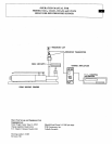
These sensors feature acceleration-compensated
piezoelectric pressure probes, mounted in a conical
end seal helium bleed adaptor.
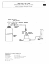
The helium gas, applied from a 1500 psi source, is
metered by a built-in orifice and flows around the
probe body and out the passage of the adaptor ahead
of the probe diaphragm. The helium gas flowing out
the passage protects the sensor diaphragm from the
hot gasses as well as increasing the natural frequency
of the passage by a factor of approximately three to
one.
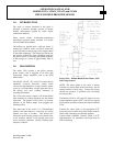
2.0 DESCRIPTION
The model 122A contains a one pC/psi pressure
probe (sensor) and is designed to be used with
electrostatic charge amplifiers such as the PCB
Model 462A.
The Models 122A21, A22, and A24 contain built-in
impedance converter electronics circuits which
convert the high-impedance voltage from the quartz
crystal to a low-impedance voltage signal that can be
fed directly into most common indicating or
recording instruments.
The 122A series sensors contain a 10 micron helium
filter contained in a fitting threaded onto the helium
input tube. The purpose of this filter is to prevent
particles in the helium supply from plugging the
metering orifice.
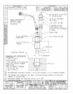
The outer body of this series is 17-4 PH hardened
stainless steel and features a conical tip for sealing
without seal rings or washers. This feature also
allows the sensor sensing passage to be placed closer
to the chamber without a long passage that could
cause resonance problems, severely limiting high-
frequency response.
Series 122A: Helium Bleed Rocket Motor, ICP
®
and Charge Sensors
NOTE: The sensor probe in this series is factory
installed at a precise depth in the outer body. Do not
attempt removal of this probe. Contact the factory
should any questions or problems arise concerning
the sensor probe.
The Models 122A21, A22, and A23 Sensors use low
output-impedance probes (ICP
) and will not require
the insulation resistance cautions described for Model
122A.
Connect the sensor cable to the appropriate ICP
power unit and check the front panel monitor meter to
check cable connections and internal amplifier.
Consult Guide G-0001B, "General Guide to ICP
Instrumentation" for installation and usage hints for
ICP
instruments.