


Copyright © 2011 Eagle Tree Systems, LLC
http://www.eagletreesystems.com
Page
3
Note that the force of gravity is 1 g. So, when configured for 2 g, the MicroSensor will easily be triggered by normal handling. For
example, lifting it at a rate that causes an additional 1 g of acceleration on the Z axis will trigger the sensor. Along these lines, it is important
to handle the sensor with care when reading the last session’s maximum values or
they could be lost and replaced.
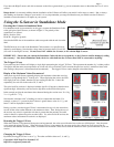
To change the G-Force trigger value, connect the Standalone Cable as described
above, but don’t power the G-Sensor. Then, connect a small piece of wire between
the unconnected pins of the Standalone Cable’s 4 pin connector, corresponding to the
brown and yellow dots on the label, as shown in Figure 2. This creates a jumper
between the brown and yellow labeled pins.
Then, power the G-Sensor via the Standalone Cable. Upon power up, the LED will display the previous G-Force trigger value, and then
flash the new value five times before beginning to display the last session’s max G-Force values. Each time the power is applied with the
jumper connected, the trigger value will increase by one, until reaching 5 g, at which time the trigger G-Force will return to 2 g. To change
the trigger value, just repeatedly disconnect and reconnect power, until the desired trigger value is flashed 5 times.
Using the G-Sensor with your eLogger V4 or V3
Windows Software and Firmware Update
To use the G-Sensor with your eLogger, you must update your software to Eagle Tree Windows Software version 9.45 or later. To
update, download the latest software from the support page of our website, located at http://eagletreesystems.com/Support/apps.htm . After
downloading and installing the software, if you have not already done so, set up the Recorder software as described in your eLogger
instruction manual. Then the firmware of your eLogger will need to be updated. To upgrade your firmware, just click “Hardware,
Firmware Control” and click the Update button for the eLogger.
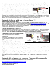
Connecting the G-Sensor to the eLogger V4/V3
The G-Sensor plugs into the “LCD/OSD” or “LCD/TX” port of your eLogger V4 or V3, as shown in Figure 3. If you have a PowerPanel
or other MicroSensors, those can “daisy chain” connect to the pins on the side of your G-Sensor, with the polarity as indicated on the G-
Sensor label. NOTE: The Standalone Cable must not be used when the G-Sensor is connected to the eLogger!
Configuring the G-Sensor with the Windows Software
Choose one or more of the G-Sensor options below:
Logging G-Force
To log G-Force, just click “Hardware -> Choose Parameters to
Log in the Recorder” and check the “3 Axis G-Force X, Y and
Z” box.
Displaying G-Force in the Windows Software
To display the G-Sensor Gauge and/or Numeric G-Force
readings, click “Software, Choose Instruments to Display on the PC Screen” and check one or more of the following:
* G-Force X Axis Meter, G-Force Y Axis Meter, and/or G-Force Z Axis Meter
* G-Force X Axis Numeric, G-Force Y Axis Numeric, and/or G-Force Z Axis Numeric
Then, after downloading data from your eLogger and clicking the “Play” button in the software, or running the eLogger in USB Live Mode,
the gauges and/or numeric displays will show the values corresponding to the G-Sensor readings.
Graphing G-Force
To graph G-Force, after downloading data from your eLogger, click “Data/2D Chart” and select G-Force X, G-Force Y and/or G-Force Z
for graphing. Also note that live G-Sensor readings can be displayed on the graph, by clicking the “Live Mode” button on the chart.
Displaying G-Force on the PowerPanel LCD
Select “Hardware, Configure PowerPanel Display”, and choose G-Force X Axis, G-Force Y Axis, G-Force Z Axis for PowerPanel
display.
Using the MicroSensor with your own Firmware/Microcontroller
Please see this document for information on using the MicroSensor with your own firmware:
http://www.eagletreesystems.com/support/manuals/microsensor-i2c.pdf