


6
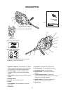
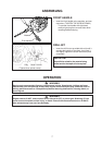
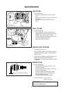
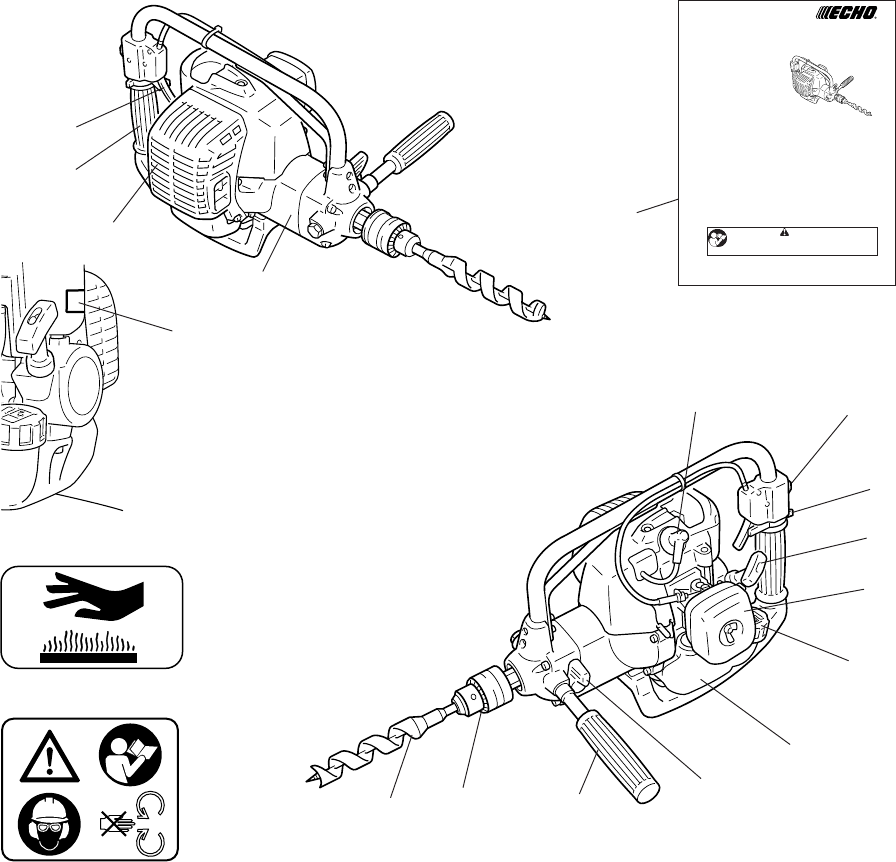
DESCRIPTION
1. Operator’s manual - Included with unit. Read
before operation and keep for future reference
to learn proper, safe operating techniques.
2. Throttle trigger - Device activated by the
operator’s finger, for controlling the engine
speed.
3. Rear handle - Handle located furthest from the
drill bit.
4. Silencer cover
5. Drill bit - Not included with unit.
6. Chuck
7. Front handle - Handle located on the front
gear case.
8. Shift lever
9. Fuel tank - Contains fuel and fuel filter.
10. Fuel tank cap - For closing the fuel tank.
11. Air cleaner cover - Covers air filter.
12. Starter handle - Pull handle to start the
engine.
13. Throttle trigger lockout - Device that
prevents the accidental operation of the throttle
trigger until manually released.
14. Ignition switch - Device for allowing the
engine to be started and stopped.
15. Spark plug
1
2
3
4
12
11
10
8
7
6
5
9
14
15
13
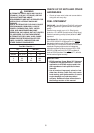
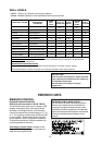
Part Number X505-002310
* If a decal cannot be read, a new one can be
ordered from your ECHO dealer.
Part Number X505-002310
Part Number X505-002570
Part Number X505-002570
OPERATOR’S MANUAL
ENGINE DRILL
EDR-260
X750-005 05 6
X750409-3606
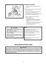
WARNING
READ INSTRUCTIONS CAREFULLY AND FOLLOW RULES FOR
SAFE OPERATION.
FAILURE TO DO SO COULD RESULT IN SERIOUS INJURY.
ECHO, INCORPORATED
400 Oakwood Road, Lake Zurich, Illinois 60047-1564
Phone : 847-540-8400
Printed in Japan 1107sf 001 ES