


2
D
Aus Verpackungsgründen muß die Bandschleifvorrichtung vom Kunden montiert werden. Dabei ist nach folgender
Beschreibung vorzugehen:
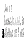
Die vormontierte Bandschleifvorrichtung (1 - 17) auf den Schleifermotor aufsetzen und festklemmen.
Die Reduzierhülse schmal (27) sowie die Topfscheibe (18) und die Reduzierhülse breit (28) auf die Motorwelle
aufschieben und mittels einer Sechskantmutter M 12 auf der Motorwelle befestigen.
Den Kugelknopf mit Gewindebolzen (24) in den Halter (5) einschrauben. Ebenso den Sterngriff (22) mit der
Rändelmutter flach M 8 (23).
- Rändelmutter flach noch nicht fest anziehen -
Die vorgegebene Laufrichtung, die auf der Innenseite des Schleifbandes (25) durch Pfeile gekennzeichnet ist, muß
eingehalten werden (siehe Bild).
Durch Eindrücken des Kugelknopfes (24) wird der Achsabstand verkleinert, nun das Schleifband (25) auf die
beiden Rollen (9 und 18) auflegen.
Die Auflage (15) in der Höhe zum Schleifband (25) ausrichten und festziehen.
Durch Drehen des Sterngriffes (22) und gleichzeitiges in Bewegung setzen des Schleifbandes (25) von Hand, wird
das Schleifband (25) ausgerichtet, bis es gerade über die Rollen läuft.
Durch Einschalten der Maschine und gleichzeitiges Nachregulieren mit dem Sterngriff (22) wird das Schleiband
(25) nochmals ausgerichtet.
Wenn das Schleifband gerade auf den Rollen läuft, wird die Rändelmutter flach M 8 (23) fest angezogen.
Schrauben Sie, zur Montage des Schutzbleches (26), die 5 Gewindeschrauben aus der Auflage (15) heraus, legen
Sie dann das Schutzblech auf und drehen die Schrauben wieder fest an.
ENG
To facilitate space saving packing, the linishing arm must be installed by the customer. Please follow the instructions
given below:
Put the pre-assembled linishing arm (1 - 17) on the motor and tighten.
Place narrow reducing bush (27), cup wheel (18) and wide reducing bush (28) on the motor shaft and secure with a
hexagon nut M 12.
Screw ball knob with threaded bolt (24) into the bracket (5), then attach the starknob screw (22) with the thin type knurled
thumb nut M 8 (23).
- Do not yet fully tighten the knurled thumb nut -
Observe the running direction, indicated by arrows on the inside of the sanding belt, when fitting a sanding belt (see
illustration).
By pushing the ball knob (24) in, the centre distance between the axis is lessened for fitting the sanding belt (25) on the
two wheels (9 + 16).
Adjust height of the tool support (15) against the sanding belt (25) and secure in position.
By turning the starknob screw (22) and moving the sanding belt (25) by hand at the same time, the sanding belt is aligned
until is runs straight on the wheels.
Final alignment is made by switching the machine on and readjusting the starknob screw (22). Once the sanding belt
(25) runs straight on the wheels, without wandering to either side, the thin type knurled thumb nut (23) is fully tightened.
To install the wheel cover (26) remove the 5 screw from the support (15), put the wheel cover in place and fasten with
the 5 screws.