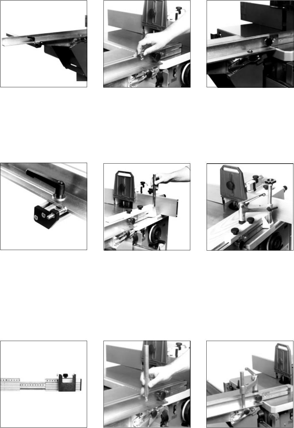
Fit slide washer into the groove of the link bracket extrusion. Insert pivot bolt and secure with
starknob screw.
Put cup square neck screws M 6x20 into the
slot of the fence extrusion an install the first
stop plate with a nyloc nut M 6. Bolt fence
extrusion to link bracket angle bar with 2
each cup square neck screws M 6x29, wash-
ers Ø 6 mm and 6 mm starknobs. Install
second stop plate.
6 Operation
After removal of the clamping plate long
workpieces are placed directly on the sliding
table and held with the clamping arm mounted
as shown at right.
The pivot bolt is replaced by the clamping
arm support provided, which is locked in
position with the starknob screw.
To work long stock the fence can be exten-
ded. Move the flipstop to the fence extension
extrusion before extending the fence.
Attach link bracket extrusion end plate (357)
with two pan head tapping screws to the link
bracket extrusion. Set fence square with the
machine's fence and set the link bracket
extrusion to the zero mark by moving it as
required.
- Exact setting is done with the setting screw.
Install support rod (375) to clamping plate
with hexagon nut M 12. Fit clamping plate to
the fence extrusion end.
Hardware:
2 ea. hexagon head screw M 6x35
2 ea. washer Ø 6
2 ea. starknob M 6 female.
Place clamping arm, with spring fitted in
groove, onto support rod and tighten ratchet
lever to hold in position.
Short work is held on the clamping plate
attached to the fence.


