


7
MODEL 381pH/ORP SECTION 2.0
INSTALLATION
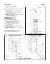
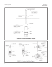
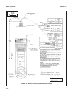
2.3 INSERTION INSTALLATION (Code 00). To install
the sensor in the side of a tank, in a pipeline, or in a
pipe “tee”, proceed as follows (see Figure 2-3):
CAUTION
Sensor must be installed within 80° of the
vertical plane (see Figure 2-3).
1. Use Teflon tape on pipe joint, and install sensor as
shown in Figure 2-3.
CAUTION
Do not use a pipe wrench on the plastic
sensor parts. Severe damage could result.
2. Tighten all fittings and sensor.
3. Refer to Section 2.6 for wiring instructions.
4. If desired, the cable may be installed in a con-duit.
Flexible conduit MUST be used at the sensor for a
short distance to permit removal for periodic main-
tenance. Use the 3/4 inch MNPT threads on the
cover to attach the conduit to the sensor.
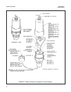
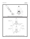
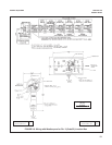
2.4 FLOW THROUGH INSTALLATION (Code 03). To
install the sensor in the flow cell proceed as follows
(see Figure 2-4):
1. Attach the flow cell’s 3/4 inch MNPT to the sample
or process line. (Note flow direction on side of flow
cell.)
2. Holding the sensor with the electrode pointing up,
seat the upper O-ring (P/N 9550146) flush with the
sensor body above the 2-inch MNPT. Lubricate
with O-ring lubricant (P/N 2001928).
3. With the coupling nut thread in place, thread the
electrode shroud onto the sensor body (see Figure
2-4), insuring that the O-ring is properly seated
and does not become pinched or twisted.
NOTE
The coupling nut must be inserted between
the lower body assembly of the sensor and
electrode shroud (see Figure 2-4).
4. Next, place the lower O-ring (P/N 9550147) in the
flow cell and lubricate with O-ring lubricant (P/N
2001928).
5. Place sensor, coupling nut and electrode shroud in
the flow cell. Insure that the O-ring is seated prop-
erly.
6. Rotate sensor until the key on electrode shroud
drops into either the “open-flow” or “guarded” flow*
position.
7. Tighten the coupling nut and the flow cell fittings.
NOTE
Electrode shroud and coupling nut should
be hand tightened only. Do not use a
wrench. When tightening process or sample
line connectors to the flow cell do not use a
pipe wrench on the flow cell. Severe dam-
age may result.
* In "guarded" flow position, solid particles in the flow
stream are diverted from electrode.
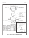
2.4.1 Installation Procedures For Low Flow
Conditions. It is extremely important that the measur-
ing electrode and liquid junction of any pH/ORP sensor
remain in contact with the process fluid at all times.
Under low flow conditions or where flow fluctuations
are common, sensor contact with the process fluid may
be interrupted unless piping procedures are followed to
prevent it.
A customer supplied valve should be installed to elimi-
nate head pressure when the sensor is being removed
from the process. This valve may also serve as a grab
sample take-off point.
The installation drawing (Figure 2-5) shows the recom-
mended piping procedures for the Model 381 pH/ORP
sensor in low flow conditions.
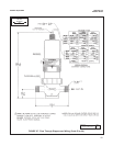
2.5 FLOW POWERED CLEANER INSTALLATION
(Code 04). To install the sensor in a flow cell with flow
powered cleaner, proceed as follows (see Figure 2-6):
1. Attach the flow cell’s 3/4 inch MNPT to sample or
process line. Note flow direction shown on the
side of the flow cell.
2. Insert the ring as shown in Figure 2-6. It should
snap in place.
3. Place the chamber into the flow cell. Notch must
be aligned for the chamber to go in place. Place
the Teflon balls (4 each) in the chamber.
4. Follow Steps 2 through 7 in Section 2.4 for sensor
installation into flow assembly (see Figure 2-4).
2.6 WIRING. Connect the wire lugs to the transmitter
terminals as shown in Figures 2-7 thru 2-10.