


Recommended pH Sensor Standardization:
For maximum accuracy, the sensor can be standardized
online or with a process grab sample after a buffer calibra-
tion has been performed and the sensor has been condi-
tioned to the process. Standardization accounts for the
sensor junction potential and other interferences.
Standardization will not change the sensor’s slope but will
simply adjust the analyzer’s reading to match that of the
known process pH.
1. While obtaining a process solution sample (it is recom-
mended that the sample is taken close to the sensor),
record the pH value that is shown on the
analyzer/transmitter display.
2. Measure and record the pH of the process solution
sample with another temperature compensated, cali-
brated pH instrument. For best results, standardization
should be performed at the process temperature.
3. Adjust the analyzer/transmitter value to the standard-
ized value.
4.3 INSTRUMENT CONFIGURATION FOR
USE WITH MODEL TF396
INSTRUMENT CONFIGURATION REQUIREMENTS: For
proper operation, instruments capable of advanced sensor
diagnostics must have this feature turned off (please refer
to the appropriate instrument's instruction manual for com-
plete instructions) .
MODEL 54epH/ORP: From the Program menu, select
Configure, then Diagnostics. Edit diagnostics and select
off.
SOLU COMP II MODEL 1055: From the Program menu,
select Measurement, then Sensor1 or Sensor2 as appro-
priate, then pH. At the screen prompt Glass Fault
Enable?, select No.
MODELS 81, 3081, 4081 OR 5081: From the Program
menu, select dIAG and toggle to OFF.
MODEL TF396 SECTION 4.0
START UP AND CALIBRATION
SECTION 4.0
START UP AND CALIBRATION
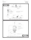
4.1 SENSOR PREPARATION.
In most cases, the pH sensor can simply be installed as shipped
and readings with an accuracy of ± 0.6 pH may be obtained. To
obtain greater accuracy or to verify proper operation, the sensor
must be calibrated as a loop with its compatible analyzer or
transmitter.
4.2 pH CALIBRATION.
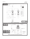
After a temporary connection is established between the
sensor and the instrument, a buffer calibration may be per-
formed. Consult appropriate pH analyzer or transmitter
instruction manual for specific calibration and standardiza-
tion procedures, or see below for recommended two-point
buffer calibration procedure.
Recommended two-point buffer calibration procedure:
Select two stable buffer solutions, preferably pH 4.0 and
10.0 (pH buffers other than pH 4.0 and pH 10.0 can be
used as long as the pH values are at least two pH units
apart).
NOTE
A pH 7.0 buffer solution reads a mV value of approx-
imately zero, and pH buffers read approximately 59.1
mV for each pH unit above or below pH 7.0. Check
the pH buffer manufacturer specifications for millivolt
values at various temperatures since it may affect the
actual value of the buffer solution mV/pH value.
1. Immerse sensor in the first buffer solution. Allow sen-
sor to adjust to the buffer temperature (to avoid errors
due to temperature differences between the buffer
solution and sensor temperature) and wait for reading
to stabilize. Value of buffer can now be acknowledged
by analyzer/transmitter.
2. Once the first buffer has been acknowledged by the
analyzer/transmitter, rinse the buffer solution off of the
sensor with distilled or deionized water.
3. Repeat steps 1 and 2 using the second buffer solution.
4. Once the analyzer/transmitter has acknowledged both
buffer solutions, a sensor slope (mV/pH) is established
(the slope value can be found within the analyzer/
transmitter).
11