


15
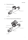
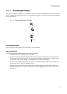
Purge Fittings
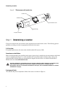
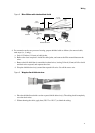
4. Connect the supply of nitrogen or argon gas to the inlet purge connection or open inlet purge line.
Leave the outlet connection open.
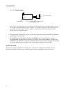
• Exercise caution to avoid introducing dirt, moisture, rust, or other contaminants into the
sensor case.
• If the purge gas is heavier than air (such as argon), locate the inlet lower than the outlet, so the
purge gas will displace air from bottom to top.
• If the purge gas is lighter than air (such as nitrogen), locate the inlet higher than the outlet, so the
purge gas will displace air from top to bottom.
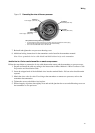
5. Make sure there is a tight seal between the inlet connection and sensor case, so air cannot be drawn by
suction into the case or purge line during the purging process.
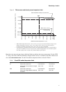
6. The purge time is the amount of time required for full exchange of atmosphere to inert gas. For each
sensor size, the purge time is different. Refer to Table 3. If purge lines are being used, increase the
purge time to fill the additional volume of the purge line.
7. Avoid pressurizing the sensor case. At the appropriate time, shut off the gas supply, then immediately
seal the purge outlet and inlet connections with the purge plugs. If pressure inside the case elevates
above atmospheric pressure during operation, the flowmeter density calibration will be inaccurate.
8. Make sure the purge fitting seals are tight so air cannot be drawn by suction into the sensor case.
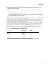
Table 3 Time required to purge T-Series sensor cases
Sensor model
Purge rate
ft
3
/hr (l/hr)
Time
(1)
minutes
(1) If purge lines are being used, increase purge time to fill the additional volume.
T025 20 (566) 1
T050 20 (566) 1
T075 20 (566) 3
T100 20 (566) 5
T150 20 (566) 10