


12
Fig. 20
Fig. 21
Fig. 22
Fig. 23
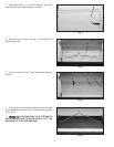
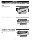
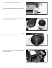
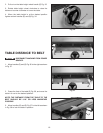
2. Move belt guard (B) down as shown in Fig. 20.
3. Remove the three screws (C) and drum plate (D) Fig.
20.
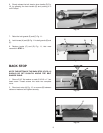
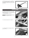
4. Align the three holes in spindle (E) Fig. 21, with the
three tapped holes (F) in the drum.
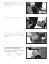
5. Insert the three screws that were removed in STEP
3, through spindle and tighten securely.
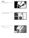
6. Insert the rod (G) Fig. 23, on the sanding spindle
table, through hole (H).
G
H
C
C
E
F
B
C
D