English
5
CHANGING THE PLANER KNIVES
WARNING: DISCONNECT THE PLANER FROM THE
POWER SOURCE BEFORE ATTEMPTING TO ACCESS
OR CHANGE THE KNIVES.
Your planer is equipped with a three-knife cutter head.
TO CHANGE PLANER KNIVES
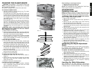
1. Use the T-wrench to remove the tool tray. The cutter
head should now be exposed.
If the eight bolts in the knife clamp ARE NOT visible, use
a piece of scrap wood to carefully rotate the cutter head
until the bolts are accessible and the cutter head locking
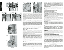
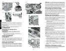
lever engages as shown in Figure 21 (O). This will pre-
vent further rotation of the cutter head as you change
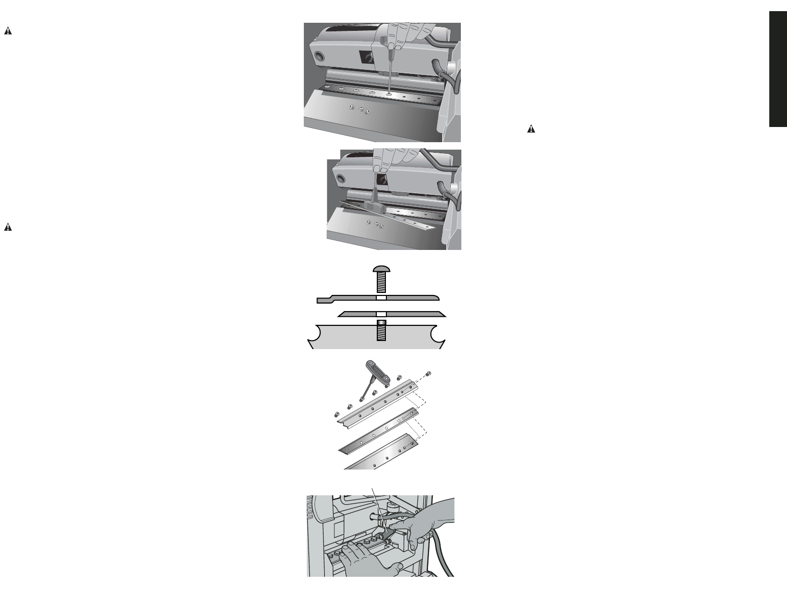
each knife (Fig. 17).
If the bolts ARE visible, be sure that the cutter head lock-
ing lever is engaged so the cutter head does not rotate
while you are changing the knives. To do this, use a
piece of scrap wood to attempt to rotate the cutter head.
The locking lever will click into place if it is not already
engaged.
WARNING: KEEP YOUR FINGERS AWAY FROM THE
CUTTER HEAD AT ALL TIMES. USE THE TOOL PROVID-
ED TO HANDLE THE KNIVES.
2. Remove bolts from knife clamp.
3. Use the magnets on the top of the T-wrench to attract the
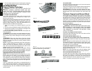
knife clamp and lift the knife off the cutter head (Fig. 18).
One of the knives should now be exposed.
4. Use the magnet on the top of the T-wrench to attract
and handle the knife. AVOID TOUCHING THE KNIFE
WITH YOUR FINGERS. The knives on your planer are
sharpened on both edges.
If only one edge of the knife is worn:
1. Turn the knife around so that the sharp, unused edge
hangs over the edge of the cutter head where it will cut
the material. Be sure to set the oblong holes in the knife
over the pins machined on the cutter head (Fig. 19).
2. To reset the knife clamp, align the beveled edge of the
knife clamp with the cutting edge of the knife (Fig. 20).
If these are not aligned correctly, the clamp will not
secure the knife properly.
3. Place the screws through the holes in the knife clamp
and knife into the cutter head.
4. Tighten the screws sufficiently.
To access and replace the other two knives:
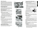
1. Depress the cutter head lock lever (O) as shown in
Figure 21.
2. Use the piece of scrap wood to carefully turn the cutter
head until it locks into place revealing another knife
clamp and dull knife.
3. Repeat the procedure indicated above.
If the knives are dull on both edges:
1. Follow the same knife change procedure indicated
above. HOWEVER, discard the dull knives and install
new ones onto the cutter head.
2. Repeat the procedure for the remaining knives.
After installing or reversing the knives:
1. Replace the tool tray onto the unit.
2. Tighten the screws onto the tray.
NOTE: THE PLANER WILL NOT OPERATE IF THE TOOL
TRAY IS NOT INSTALLED CORRECTLY.
MAINTENANCE
Installing a new belt
NOTE: No tools are necessary to install a belt. The use of a
screwdriver or other tool to pry or stretch a belt may cause
damage to the pulleys and ultimately destroy the new belt.
WARNING: TURN OFF THE PLANER AND DISCON-
NECT IT FROM THE POWER SOURCE.
1. Remove the crank handle.
2. Remove the two Allen screws from the top, right side of
the planer.
3. Remove the two, small Phillips head screws securing
the side panels to the top of the planer.
4. Lift the side panel up out of the slot in the base and
remove the panel from the machine. Notice the grooves
inside the belt.
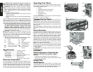
5. Start the belt on the top pulley (P) with 3 grooves on the
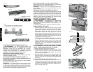
pulley, as shown in Figure 22.
6. Guide the belt between the lower pulley and the height
adjustment screw (Q), as shown in Figure 23.
7. With three grooves engaged on the large pulley, rotate
the pulley clockwise. Keep pressure on the edge of the
belt to keep the grooves engaged on the small pulley.
8. Continue pressure on the side of the belt and rotate the
large pulley while hopping the belt further onto the pul-
leys, as shown in Figure 24.
9. All of the belt grooves should be engaged in the final
position and the pulleys should rotate smoothly.
10. Reinstall the side cover and the screws. Do not over-
tighten the self-tapping screws.
Calibrating the Depth Adjustment
Scale
The depth adjustment scale on your planer is set at the fac-
tory. However, with extended use, the depth adjustment
scale could show an incorrect measurement.
TO CHECK THE DEPTH ADJUSTMENT SCALE
1. Plane a piece of wood, noting the measurement on the
depth adjustment scale.
2. Measure the finished thickness of the workpiece.
3. If the thickness of the workpiece does not match the
reading on the depth adjustment scale, loosen the two
Phillips head screws (R) shown in Figure 25.
4. Adjust the pointer up or down until its reading matches
the finished thickness of the workpiece. Securely
re-tighten the screws.
Leveling the Table Extensions
After extended use, the table extensions might become
slightly out of level. To ensure that the tables are level, place
a straight edge on the table extension. The straight edge
FIG. 20
O
FIG. 21
FIG. 17
FIG. 18
FIG. 19


