


787
Users Manual
22
Simulate Mode
Simulate mode is so named because the meter simulates
a current loop transmitter. Use simulate mode when an
external dc voltage of 24 to 30V is in series with the
current loop under test.
Caution
Set the rotary switch to one of the mA output
settings BEFORE you connect the test leads
to a current loop. Otherwise, a low
impedance from the other rotary switch
positions could be presented to the loop,
causing up to 50 mA to flow in the loop.
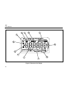
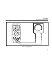
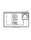
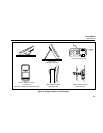
Simulate mode is selected automatically by inserting the
test leads into the SIMULATE + and − jacks as shown in
Figure 8. Simulate mode conserves battery life, so use it
instead of source mode whenever possible.
The display looks the same in source and simulate
modes. The way to tell which mode is in use is to see
which pair of output jacks is in use.
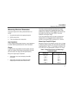
Changing the Current Span
The meter’s current output span has two settings (with
overrange to 24 mA):
• 4 mA = 0%, 20 mA = 100% (factory default)
• 0 mA = 0%, 20 mA = 100%
To find out which span is selected, short the OUTPUT
SOURCE + and − jacks, turn the rotary switch to
OUTPUT [ mA, and observe the 0% output level.
To toggle and save the current output span in nonvolatile
memory (retained when the power is turned off):
1. Turn off the meter.
2. Hold down the Kpushbutton while you turn the
rotary switch to OUTPUT [ mA.
3. Wait at least 2 seconds, then release K.