


June 2004 © 2004 Foundry Networks, Inc. 2 - 1
Chapter 2
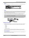
Installing and Configuring Rack-Mounted Systems
Before You Begin
Unpacking and Inspecting
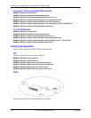
The following items are shipped with these systems.
If any of the above items are missing or defective, contact Foundry.
Additional Cables, Tools, and Materials
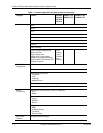
The following additional cables are required for integrating these systems with other networking devices.
• RJ-45, male/male, Category 5, shielded, twisted pair cable (Ethernet ports)
• RJ-48C, male/male, shielded, straight-through cable (T1/E1 ports)
• RG-59 coaxial cables with BNC connectors (Clear Channel DS3 and CT3)
The following tools are required for installation.
• #3 Phillips screwdriver (rackmount)
• #2 Phillips screwdriver (mounting bracket)
• 1/8 inch (3 mm) flat-blade screwdriver (DC power, ground, and external alarm)
• wire stripping tool (DC power and external alarm)
The following additional materials are required for connecting DC power, ground, and external alarms to the
Foundry system.
• 18-22 AWG wire (external alarm and ground)
• 18 AWG wire (DC power)
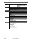
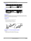
Foundry system Two 19-inch (48.26 cm) rack-mount brackets
AC power cord Two 23-inch (58.42 cm) rack-mount brackets
RJ-45 console cable Four #6 screws
Male DB-9 modular adapter Four each #6 flat washers and #6 lock washers
Female DB-9 modular adapter Product Documentation CD-ROM
Four self-adhering rubber feet Registration card
Quick start guide Warranty form