


23
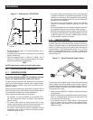
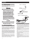
2.1.3 SUSPENDED MOUNTING
If planning to suspend the generator below the horizontal sup-
port tubing, the suspension method to use with the vehicle frame
members must (a) be able to support the weight of the generator
AND (b) provide sufficient restraint for the generator. One typical
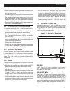
suspended mounting system is shown in Figure 2.2. The location
of a suspended mounting system must be carefully planned, keep-
ing the following general rules in mind:
Protect the generator against road splash and debris. Baffles or •
splash guards may be required to protect certain areas of the
generator. To make sure the generator is adequately protected,
road test the installation through mud, water and slush.
Figure 2.2 – Typical Suspended Mounting System
The installer must make certain that the selected location will •
permit adequate cooling and ventilating airflow to be supplied.
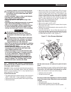
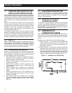
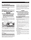
2.1.4 GENERATOR RESTRAINT
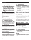
Use four 3/8"-16 hardened steel bolts (Grade 5) to fasten the
generator to the supporting frame or the support tubing. These
bolts must pass through (a) the generator mounting base, (b) the
compartment floor (if a compartment is used) and (c) the support-
ing framework (Figure 2.3). All bolts must be long enough so that
when tight, at least three threads are visible past the retaining lock
nuts. Refer to "Generator Compartments" for the location of the
generator mounting holes. Torque Bolts to 31 ft./lbs..
Figure 2.3 – Typical Generator Restraint
2.2 GENERATOR COMPARTMENTS
Whether the generator set is being installed inside a compartment
specifically manufactured to house a generator or inside a compart-
ment that the installer constructs, the compartment MUST meet
certain specifications as outlined in the following sections:
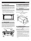
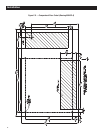
2.2.1 COMPARTMENT SIZE
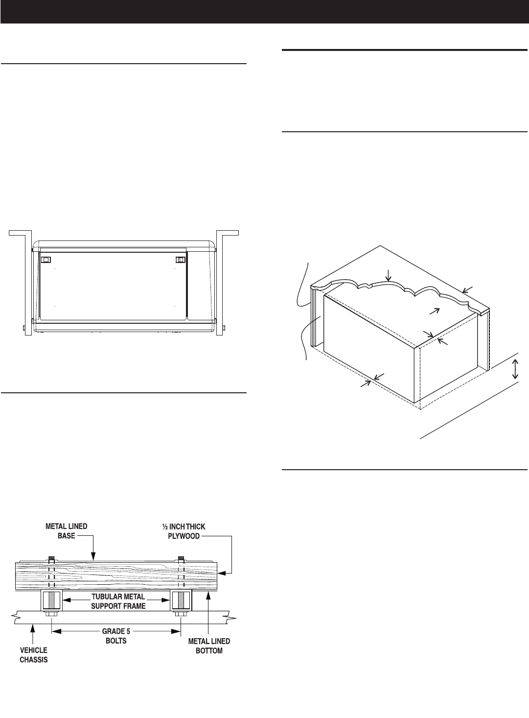
Plan the compartment size carefully. Provide a minimum clearance
of 1/2 inch (13 mm) on the front top, sides, and from the back for
air circulation AFTER the compartment has been lined with metal
and sound insulation (Figure 2.4).
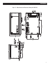
NOTE:
Refer to “Figure 1.2 – Major Features and Dimensions”.
Figure 2.4 – Clearances
1/2" Clearance
in Back
1/2" Clearance on Top
1/2" Each Side
1/2"
in Front
Insulation
Plywood
Compartment
18" Clearance Recommended
Below (Minimum 12")
2.2.2 COMPARTMENT CONSTRUCTION
The generator compartment should be either constructed of, or •
lined with, 26-gauge galvanized steel.
NOTE:
Aluminum is NOT an acceptable alternative to galvanized steel
due to aluminum’s low melting point.
If the compartment is lined with galvanized steel, it may be •
constructed of any material. The manufacturer recommends
that the compartment be constructed of 1/2-inch thick plywood
(not strandboard), with the floor made of a double thickness of
1/2-inch plywood with the grain of the wood at cross section
for added strength (Figure 2.5).
If constructing a compartment, line the exterior (underside) of •
the compartment floor with 26-gauge galvanized steel.
All seams, splices and joints of the compartment walls (unless •
vapor tight by design) should be caulked to prevent poison-
ous, flammable or explosive vapors from entering the vehicle
interior.
Installation