


32
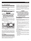
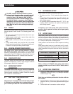
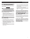
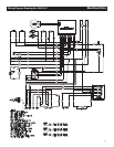
Figure 2.16 – Connecting Battery Cables
—
+
Battery
Negative Cable
Positive Cable
Chasis Ground
2.7.4 BATTERY COMPARTMENT
Install the generator battery in its own, vented compartment. Place
the battery compartment away from any source of heat, sparks
or flame.
Provide ventilation openings in the battery compartment. The
minimum size of openings should be two (2) square inches at
the top of the compartment. Mount the battery on a strong, rigid
supporting structure, where leaks and spills of battery fluid will not
cause damage.
2.8 OPTIONAL ACCESSORIES
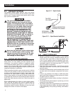
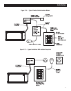
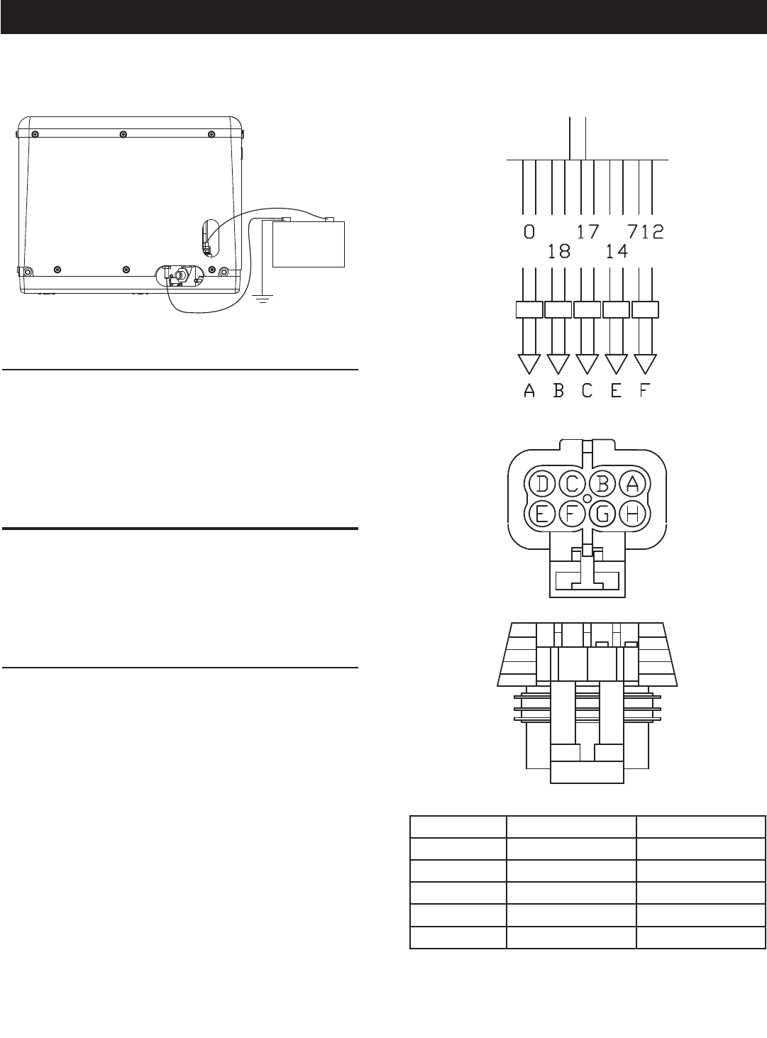
A plug-in receptacle (Figure 2.17) is provided on the generator set.
Use this receptacle to connect an optional remote-mounted start/
stop panel to the generator. Installation of such a panel will permit
starting and stopping the generator engine from any convenient
location inside the vehicle.
2.8.1 REMOTE PANEL MODELS
The remote panels mount a rocker type start/stop switch, a
“Generator Run” advisory lamp and an hourmeter. The hourmeter
should be used in conjunction with the maintenance operations
found in Part I of this manual.
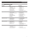
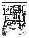
Figure 2.17 – Remote Panel Plug-in Receptacle
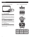
WIRE NO. WIRE COLOR FUNCTION
0 Black Ground
14 Blue Engine Run Signal
712 Blue 12 VDC
17 Brown/White Start
18 Brown/Black Stop
Installation