


1
2
3
4
5
6
7
8
NM L K J I H G F E D C B A
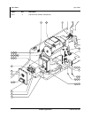
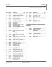
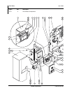
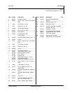
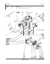
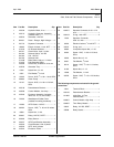
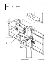
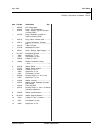
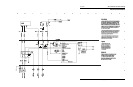
Part No. 106730 Welder Supplement
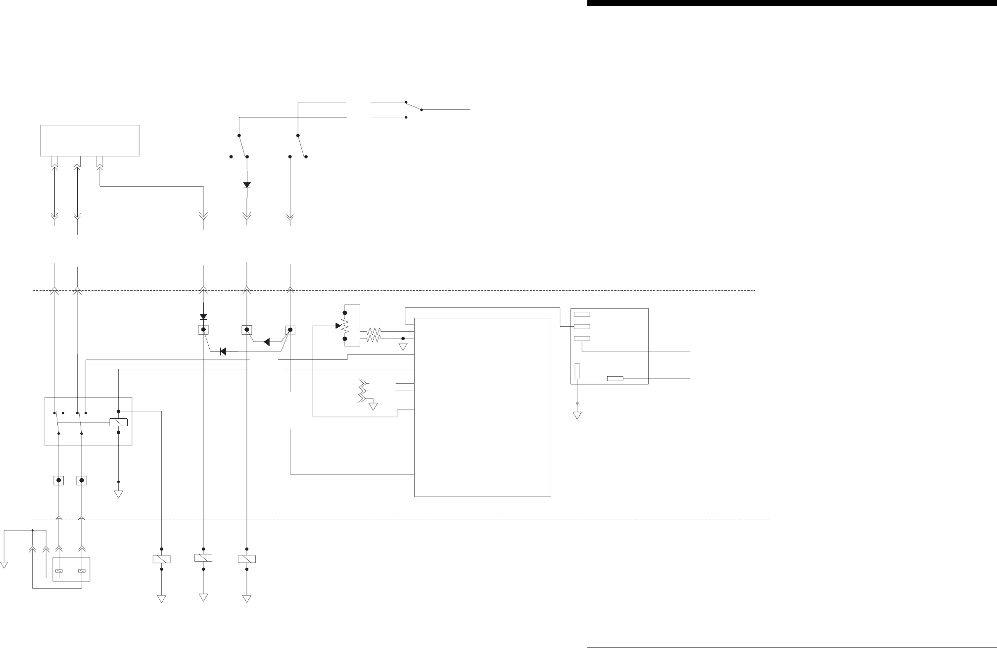
Electrical Schematic
July 2004 200 • Schematics and Hose Drawings
DRIVE EDC REVERSE
DRIVE
EDC
REVERSE
DRIVE EDC FORWARD
DRIVE
EDC
FORWARD
B
C
U4
A
D
C5-21
C5-20
C1B-5
C1B-4
C31EDC WH/BK
C31EDC
WH/BK
C30EDC WH
C30EDC
WH
C1P-5
C1P-4
C45GEN GR/WH
C45GEN
GR/WH
TB45
TS47
P25FS-RD
P24FS-WH
TS4
TB35
C35RPM BK/RD
C35RPM
BK/RD
C1B-9
C1P-9
RPM HI
RPM
HI
GENERATORON
GENERATOR
ON
D12
RPM LO
RPM LO
FOOTSWITCH
TB31 TB30
2
4
6
8
1
3
5
7
RS232RxD
A1 BATTERY+
A1 BATTERY+
A2 SENSOR POWER +5 VDC
A2 SENSOR POWER +5 VDC
A3 BATTERY-
A3 BATTERY-
B1 VALVE 0 FWD COIL
B1 VALVE0 FWD COIL
B2VALVE1NC
B2 VALVE1 NC
B3 DIGITALOUTPUT BYPASS/OMRON
B3 DIGITALOUTPUT BYPASS/OMRON
C1 TxD
C1 TxD
C2 RxD
C2 RxD
C3 /BOOT
C3 /BOOT
D1 ANALOG 0 JOYSTICK
D1 ANALOG 0 JOYSTICK
D2 ANALOG 1 NC
D2 ANALOG 1 NC
D3 DIG IN 3 NC
D3 DIG IN 3 NC
E1 NOT USED
E1 NOT USED
E2 NOT USED
E2 NOT USED
E3 NOT USED
E3 NOT USED
F1 DIG IN 0
F1 DIG IN 0
F2 DIG IN 1 GENERATOR ON
F2 DIG IN 1 GENERATOR ON
F3 DIG IN 2
F3 DIG IN 2
RS232TxD
RS232TxD
CR4
HIGH IDLE
HIGH
IDLE
RELAY
C45GEN GR/WH
C45GEN
GR/WH
V151HG GN
V151HG GN
V150HG GN/BK
V150HG GN/BK
1k ohms
1k ohms
124 ohms
124 ohms
124 ohms
124 ohms
Adjustments
1. Connect a digital multimeter
1. Connect a digital multimeter
(DMM) with a frequency counter to
(DMM) with a frequency counter to
the 110 vac outlet. Adjust the
the 110vac outlet. Adjust the
potentiometer until a frequency of
potentiometer until a frequency of
66.5 HZ is obtained with no load
66.5 HZ is obtained with no load
on the generator.
on the generator.
A
B
C
P26FS-BK
TB29
2
1
3
C1B-3
C1P-3
C29MS RD/WH
C29MS
RD/WH
BYPASS
VALVE
MOTOR STROKE
MOTOR
STROKE
VALVE
SX Controller
SX Controller
RELAY
8N.C.
8 N.C.
2COM
2 COM
1N.O.
1 N.O.
3 GND
3 GND
5 SW INPUT
5 SW INPUT
TIME DELAY
TIME DELAY
MODULE 4S
MODULE 4S
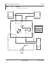
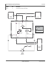
Modification note
Modification note
Replace two position terminal strip #45 and use 74911
Replace two position terminal strip #45 and use 74911
four position terminal strip in its place. Use the
four position terminal strip in its place. Use the
name plate from the old two position terminal.
name plate from the old two position terminal.
Add three Genie P/N 45762 6 amp 200 PIV diodes in
Add three Genie P/N 45762 6 amp 200 PIV diodes in
the position shown in the schematic.
the position shown in the schematic.
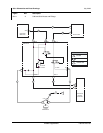
Theory of Operation
Theory of Operation
1. Turning on the Generator supplies current to the high idle relay
1. Turning on the Generator supplies current to the high idle relay
through the diode switching the engine to high RPM. In addition
through the diode switching the engine to high RPM. In addition
the diode between TB45 and TB29 supplies power to the motor
the diode between TB45 and TB29 supplies power to the motor
stroke valve switching the motors to high speed/low torque mode.
stroke valve switching the motors to high speed/low torque mode.
2. The SX controller is turned ON supplying power to bypass valve
2. The SX controller is turned ON supplying power to bypass valve
and the change over relay. The EDC valve is switched over to
and the change over relay. The EDC valve is switched over to
the output of the SX controller.
the output of the SX controller.
3. When the AC generator is turned OFF the SX module will ramp
3. When the AC generator is turned OFF the SX module will ramp
the output to the EDC to threshold preventing cavitation to the
the output to the EDC to threshold preventing cavitation to the
hydraulic motor powering the generator. When threshold is
hydraulic motor powering the generator. When threshold is
reached the bypass valve is turned OFF.
reached the bypass valve is turned OFF.
4. The time delay module keeps the SX controller ON for four
4. The time delay module keeps the SX controller ON for four
additional seconds after the ESTOPis pressed allowing for a
additional seconds after the ESTOPis pressed allowing for a
controlled ramp down of the generator.
controlled ramp down of the generator.
TO TB#24
TO TB#24
TO TB#23
TO TB#23
PLATFORM
GROUND
CR46
16
15
ALC-500
20
C2P-7
C2B-7