13
2. Remove the collet (5) and
replace with the desired
collet (fig. F). The size of
the collet will depend on
the shaft diameter of the
accessory to be used.
3. Press the spindle lock
button (2) and hand tighten
the collet nut (3) by turning
it in a clockwise direction.
Changing accessories
WARNING. If the accessory has not been inserted as far as
possible there may be too much shaft exposed which could
cause the bit to damage and/or bend.
IMPORTANT. Ensure the machine is switched off and the
plug is removed from the power before you commence
accessory changeover.
Note. Loosen and tighten the collet nut (3) with your hands.
Never tighten the collet nut (3) with the use of pliers or any
other clamping device as the collet nut (3) may strip.
Always ensure bits are tight before commencing any work
with your tool.
1. Turn the collet nut (3) in an anti-clockwise direction to
loosen and, when loose, insert the desired rotary tool
piece into the collet (5).
Note. If the shaft of the rotary tool is too large to fit into the
collet (5) or fits too loosely, it is necessary to change the
collet. Refer to ‘Changing the collet’ of this manual
for instructions.
2. Whilst depressing the spindle lock button (2), hand
tighten the collet nut (3) by turning it clockwise until tight.
Note. If the rotary tool piece is not spinning, yet the collet
nut (3) is spinning, the collet nut (3) may need to be
tightened further.
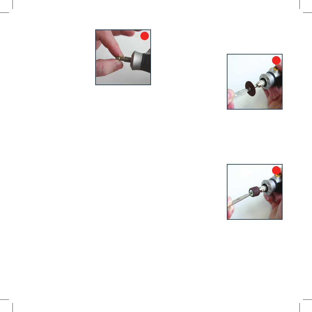
Locating a cutting /sanding disc
1. Locate an appropriate disc mandrel (holder) into
the collet (5).
2. Remove the screw from
the end of the disc mandrel
with the 2-in-1 wrench by
turning in an anti-clockwise
direction (fig. H).
3. Place a cutting/sanding disc
onto the screw of the disc
mandrel (placing one of the
rubber washers provided
with the disc mandrel on
either side of the for protection).
4. Place the screw, with the disc onto the disc shaft and
tighten with the 2-in-1 wrench by turning the screw in
a clockwise direction (Do not over-tighten as the disc
will crack).
Locating a sanding drum
1. Loosen the small screw on
the sanding drum mandrel
(holder) with the 2-in-1
wrench by turning it anti-
clockwise (fig. I). This will
allow the rubber to slacken
and allow the sanding drum
to slide onto the sanding
drum holder.
3. Slide the sanding band onto
the sanding drum mandrel.
4. Secure the sand drum mandrel in place by tightening the
screw on the top of the sanding band mandrel with the
use of the 2-in-1 wrench by turning clockwise.
Note. Tightening the screw on the sanding band mandrel
will cause the rubber to bulge and grip the sanding band.
Do not over-tighten.
H
I
F