


Pinion Assembly/Clutch Armature/Clamp
332919C 33
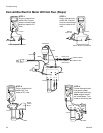
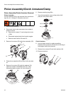
Installation
Clutch Armature
1. Lay two stacks of two dimes on smooth bench sur-
face.
2. Lay armature (25) on two stacks of dimes.
3. Press center of hub (26) down to bench surface.
4. Install armature (25) on engine drive shaft.
5. Install four screws (23) and lock washers (24) with
torque of 125 in-lb.
Pinion Assembly
1. Check o-ring (29d) and replace if missing or dam-
aged.
2. Tap pinion shaft (29a) in with plastic mallet.
3. Install retaining ring (29b) with beveled side facing
up.
4. Place pinion assembly on bench with rotor side up.
5. Apply thread sealant to screws. Install four screws
(28) and lock washers (24). Alternately torque
screws to 125 in-lb until rotor is secure. Use
threaded holes to hold rotor.
6. Install pinion assembly (29) with four screws (36)
and washers (37).
7. Connect clutch cable connectors to inside of pres-
sure control.
Clamp Removal
1. Remove engine.
2. Drain gasoline from tank according to Honda man-
ual.
3. Tip engine on side so gas tank is down and air
cleaner is up.
4. Loosen two screws (24) on clamp (22),
5. Push screwdriver into slot in clamp (22) and remove
clamp.
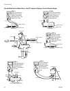
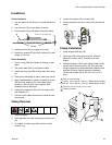
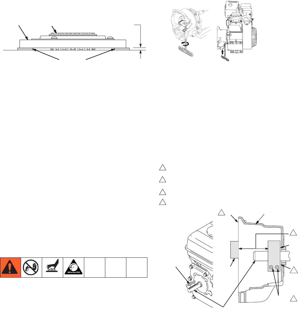
Clamp Installation
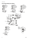
1. Install engine shaft key (18).
2. Tap clamp (22) onto engine shaft (A). Maintain
dimension shown note 2. Chamfer must face
engine.
3. Check dimension: Place rigid, straight steel bar (B)
across face of clutch housing (19). Use accurate
measuring device to measure distance between bar
and face of clamp. Adjust clamp as necessary.
Torque two screws (24) to 125 ±10 in-lb (14 ±1.1
N•m).
0.12+01 in (3.0+.25 mm)
25
26
dimes
ti6321a
ti6199a
"
!
TIA
19
4
3
2
1
Face of clutch housing
1.550 ± .010 in. (39.37 ± .25 mm) - GMAX 3400 and 3900
2.612 ± .010 in. (66.34 ± .25 mm) - GMAX 5900 and 7900
Torque to 125 ±.10 in-lb (14 ±1.1 N•m)
Chamfer this side