


. ..
This
equipment
has
been carefully manufac-
AIR
REQUIREMENTS
ranted against defective
materials
and/or uork- from
x)
to
1oo.s.i.
CAUTION:
Do
not
use
more
tured to exacting
GRACO
standards.
It
is
WW-
Air
pressures required to owrate
PmP
range
manship
as
set
forth
in
the
GRACO
WARRANTT.
than
100
lb. of air Dressure to ODerate
PWP.
Excessive
wear
due to passage of abrasive
or
not be construed
as
indication of defective parts ing pressures and operating speeds.
this
dt
corrosive
materials
through
this
equipment
shall
h-ing
continuous operation,
at
nod
m-k-
within the limitations of
this
warranty. require actual
air
delivery of approxhatew
h
IMPORTANT
NOTES
c.f.m.
per
gun
plus
3
c.f.m.
for
continuous
use
of
agitator.
"
materkl
hose
is
expensive.
HANDLE
To provide reserve capacity for
peak
load
WPPH
CARE.
GRACO
WARRANTI
does not cover abuse conditions compressor should delivery 25% me
air
such
as
sharp
khking,
crimping
or
crushing.
ment which
it
is
to
serve.
than
required
for
normal
operation
Of
all
equip-
hire to effectively ground the
unit.
If
addi-
Air
supply hose 205-216 Includes
a
static
tional
air
supply hose
is
required,
it
should
be
of
the sane type.
since
in
this Hvdra-Sorap process air
is
not need-
ed to atomize the
paint.
N&:
Consumtion of compressed
air
is
lm,
PREPARATION FOR OPERATION
1.
Remove contents arton
and
cokzct before reaching unit.
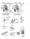
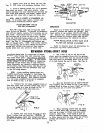
NOTE:
A
Graco
air
line
the hire-braided hpont " lined
material
strainer
2OL-999 (accessory) may be purchased
hose 205-349 (15')
or
204-938 (25'
)
to nipple separately for removing foreign
matter
from
air
164-672 protruding
from
material outlet manifold entering
the
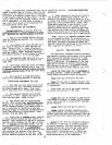
unit. Attaches to
air
manifold
205-485. Connect the end, without swivel 2QL-9LO 162-376 as shorn
in
Fig.
2.
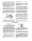
attached, to nipple 164-672. See
Fig.
1.
DO
NOT
connect swivel 204-940, attached to other end
of
205-216--
I
e'
NBT
this hose, to spray
gun
at
this
time.
DO
NOT
USE
THREAD
SEM
AT
ANY
WIVF,L
CONNECTION.
*THESE
ARC
bCCtSSCUIU
2
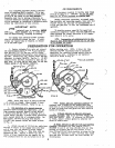
NOTE:
Check
dump
valve of
manifold
205-485
...
it
should be closed. When closed,
its
knob
is
in
a
horizontil position. Refer to
Fig.
1.
NOTE:
Models 226-163. 226-165
&
226-167 are
vith foot
on
rod protruding from bracket attached
equipped with
a
brake-to set brakes push
down
2. For operation
of
a
second sprav
mn
to back of truck base and guide rod into notch at
purchase these accessories separately...two
(2)
bottom of bracket.
high
pressure
material
shutoff valves 205-583.
a second hose 205-349 (15')
or
2OL-938 (25'),
a
L.
If
Model 226-161
or
226-163 with hand-
second swivel 2OL-940,
a
second spray
ep
205-162 merated elevator,
lift
up
on
elevator hanger and
and
a
second spray tip of
customers
choice.
Re-
hook over handle.
NOTE:
If
elevator
is
difficult
move nipple 16L-672 and plug from manFfold to raise, apply a little grease to exterior
sur-
M5-485, and qonnect valves and hoses
as
shorn faces of handle ends.
~. .
.~
in
Fig.
2.
..
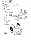
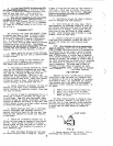
3. Attaah one end
of
15
foot air supply hose elevator, disconnect
air
line coupler 202-417,
205-216
to
smce of air Supply and screw other attached to end of air hose 160-023,
from
ab line
end
Of
hose
into
air manifold swivel adapter fitting
in
agitator 205-307 and connect to
air
162-376.' Refer to Fig.
1.
Kale hose studs are line fitting
157-367.atop
elevator as shown
in
Fix.
threaded
NET.
Install a
master
air valve
(drain
or
bleed typelin the air supply
line
in
1.
With air admitted to unit, elevator will raise
unit and hold
it
there until air hose
160621
is
Snch location
that
air
can be turned
on
and off
disconnected.
If
Model 226-165
or
226-167 with air-operated
4
PTFE
PTFE
PTFE
PTFE
PTFE
PTFE