


Installation
2 3A0293C
Installation
Prepare the Site
NOTE: Always use Genuine Graco Parts and Acces-
sories, available from your Graco distributor. If you
supply your own accessories, be sure they are ade-
quately sized and pressure rated for your system.
Bring a compressed air supply line from the air com-
pressor to the pump location. Be sure all air hoses are
properly sized and pressure-rated for your system. Use
only electrically conductive hoses. The air hose should
have a 3/4 npsm(m) thread. Before installing any air line
components, blow out the air lines to remove scale and
other debris. Use pipe compound or tape sparingly and
only on male threads.
Install a bleed-type shutoff valve in the air line upstream
from all other air line components, to isolate them for
servicing.
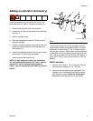
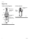
Kit Components (page 7)
Bleed-Type Master Air Valve (3)
Relieve air trapped between it and the air motor when
the valve is closed. Be sure the bleed valve is easily
accessible from the pump, and is located downstream
from the air filter/regulator (1). F
IG. 2
Air Filter/Regulator (1)
Controls pump speed and outlet pressure by adjusting
the air pressure to the pump. It also removes harmful
dirt and moisture from the compressed air supply.
Locate the regulator as close as possible to the equip-
ment it serves, but upstream from the bleed-type mas-
ter air valve (3). Install the regulator in the air line so the
air flow is in the direction of the arrow stamped on the
body. F
IG. 2.
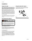
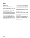
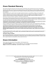
Using the Pipe Port Inserts
To open the pipe port insert (A), remove the insert pin
(S) and pull insert up in direction away from pin hole.
Install new insert and reinsert pin.
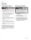
Use the bleed-type master air valve (3) to relieve air
trapped between it and the pump when the valve is
closed. This helps reduce the risk of serious injury,
including fluid injection and splashing of fluid in the
eyes or on the skin, and injury from moving parts if
you are adjusting or repairing the pump.
FIG. 1
ti1249a
A
S