


Gun Repair
30 312900G
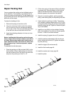
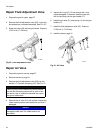
Repair Packing Rod
You may replace the packing rod as individual parts or
as an assembly. The assembly is pre-adjusted at the
factory for proper air lead and lag. The gun begins emit-
ting air before the fluid is discharged and the fluid stops
before the air flow stops.
To adjust the lead/lag air flow:
1. Remove the spring (4) from the nut (E).
2. Use a hex wrench to hold the end of the packing
rod. Turn the nut (E) out to increase the lead/lag
time for the air flow. The recommended adjustment
is one half turn and not more than one full turn.
3. Apply thread-locking adhesive to fix the nut in the
new position.
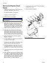
Before installing the fluid packing rod into the gun
barrel, make sure the internal surfaces of the barrel
are clean. Remove any residue with a soft brush or
cloth. Check the inside of the barrel for marks from
high voltage arcing. If marks are present, replace
the barrel.
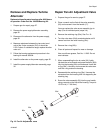
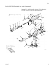
To assemble the individual parts:
1. Place the packing nut (26g) and seal (26f†) on the
fluid rod (26a). Flats on the packing nut must face
the back of the fluid rod. The seal o-ring must face
away from the packing nut. See F
IG. 15.
2. Fill the inner cavity of the spacer (26e†) with dielec-
tric grease (40). Place the spacer on the fluid rod
(26a) in the direction shown. Generously apply
dielectric grease to the outside of the spacer.
3. Place the rod packing (26d†), packing spreader
(26c†), and housing (26b) on the packing rod (26h).
4. Lightly tighten the packing nut (26g). The packing
nut is properly tightened when there is 3 lb (13.3 N)
of drag force when sliding the packing housing (26b)
assembly along the rod. Tighten or loosen the pack-
ing nut as needed.
5. Install the o-ring (26h†) on the outside of housing
(26f). Lubricate the o-ring with non-silicone grease,
Part No. 111265. Do not over-lubricate.
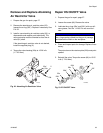
6. Install the spring (4) against the nut (E) as shown.
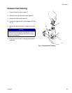
7. Install the packing rod assembly (26) into the gun
barrel. Using the multi-tool (37), tighten the assem-
bly until just snug.
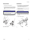
8. Install the trigger (30) and screws (8).
9. Install the fluid needle page 28.
10. Install the nozzle and air cap, page 28.
11. Install the probe.
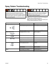
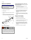
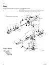
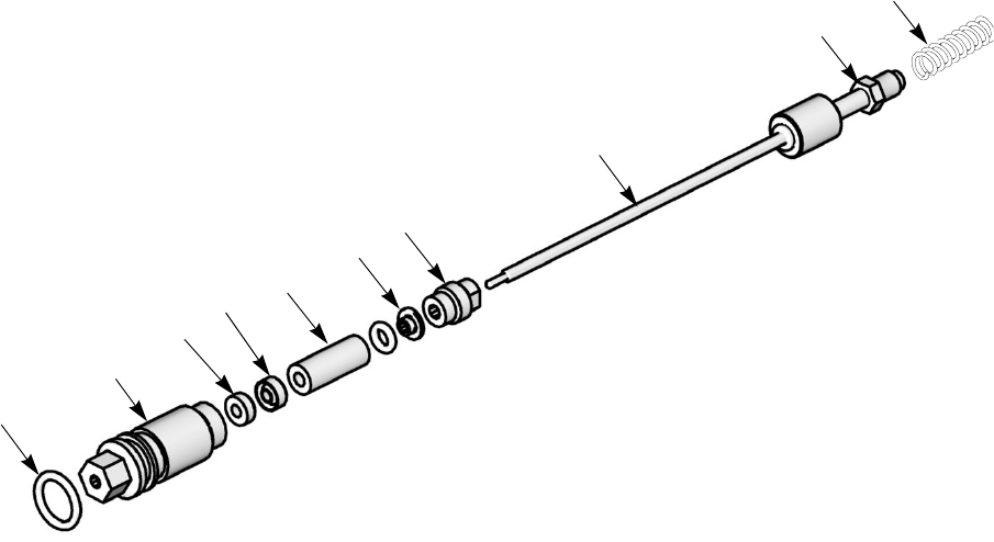
Fig. 15. Packing Rod
26h†
26f†
26c†
26d
†
26g
26b
26e†
26a
E
4
ti12719