


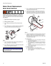
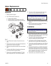
Motor Replacement
309977H 15
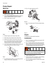
Motor Replacement
Removal
1. Relieve pressure; page 6.
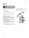
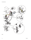
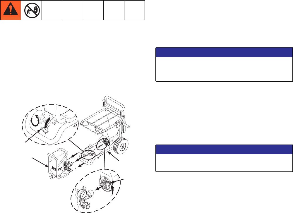
2. Fig. 5. Remove pump module (A).
a. Loosen clamp rod (20).
b. Release hopper quick-release clamp (28).
c. Disconnect pump module (A) from frame (35).
FIG.5
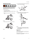
3. Fig. 6. Remove six screws (12) and motor cover
(18).
4. Remove two screws (41) and disconnect leads from
capacitor (42) to control board (38).
5. Disconnect two yellow leads (B) from control board
(38).
6. Pull strain relief (49) out of bracket and thread yel-
low leads connector through bracket.
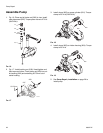
7. Remove four screws (90) and washers (71) from
gear housing base (25), Parts Drawing, page 26.
8. Tip motor and drive housing assembly back and
remove two screws (86) and washers (84).
9. Return motor and drive housing assembly to vertical
position.
10. Remove screws (85) and washers (84). Remove
motor (33) from drive housing (37).
Installation
1. Fig. 6. Place new motor (33) on drive housing (37).
Rotate fan (C). When gears are felt to mesh, install
four washers (84) and screws (85).
2. Tip motor and drive housing assembly back and
install two washers (84) and screws (86).
3. Install motor and drive housing to gear housing
base (25) with four screws (90) and washers (71).
4. Thread yellow lead (B) through strain relief (49) and
connect to control board (38). Install strain relief in
bracket.
5. Connect red brush lead (+) and black brush lead (-)
according to markings on the motor and capacitor.
Install brush lead ends and wire harness (155) lead
ends to capacitor with screw (41). See Wiring Dia-
gram, page 29 to verify polarity is correct.
6. Install motor cover (18) with five screws (12).
WLD
$
NOTICE
Do not drop gear cluster (D) when removing drive
housing (37). Gear cluster may stay engaged in
motor front end bell or drive housing.
NOTICE
When installing motor, carefully align gears to avoid
damaging mating parts.