


Operation
309032L 3
Operation
Pressure Relief Procedure
Follow the Pressure Relief Procedure whenever
you see this symbol.
1. Close the supply pump’s bleed-type master air valve
(required in pneumatic systems).
2. Open the dispensing valve until pressure is fully
relieved.
3. Open the fluid drain valve at the pump fluid outlet.
Leave the drain valve open until you are ready to
use the system again.
NOTE: If you suspect the dispensing valve, extension,
or grease fitting coupler is clogged, or the pressure has
not been fully relieved after following the previous steps,
using a rag VERY SLOWLY loosen the coupler or hose
end coupling and allow pressure to be relieved gradu-
ally, then loosen the part completely then clear the clog.
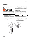
Adjustment
The dispense valve provides positive control of high
pressure lubricants. When supplied with air the pump
will start when the valve is triggered and still stall against
pressure when the trigger is released.
1. Relieve the pressure, see Pressure Relief Proce-
dure.
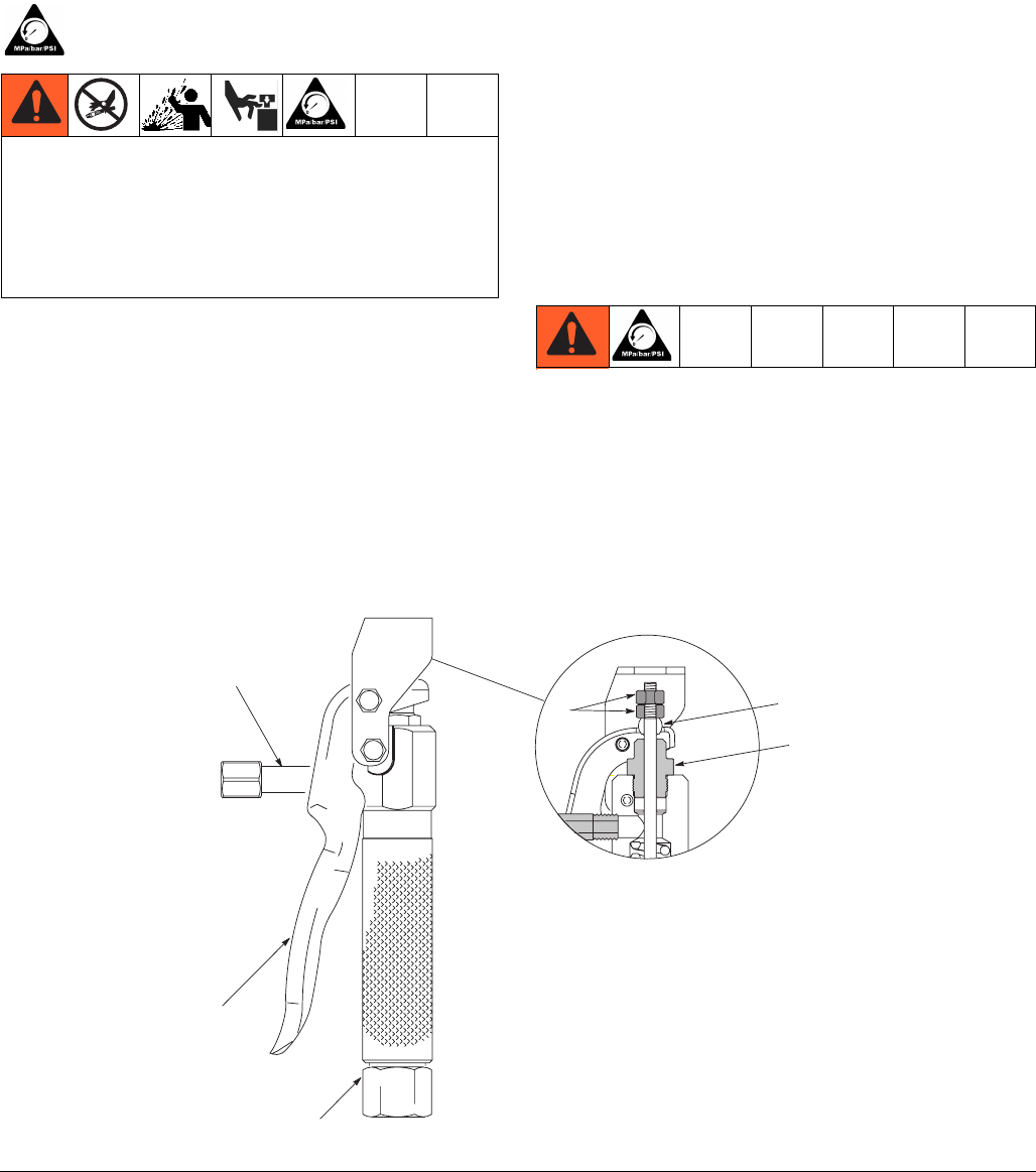
2. To adjust the clearance, loosen the top nut (5, Fig 1)
and turn the bottom nut (5) in or out as needed. To
increase grease flow turn bottom nut in. To reduce
grease flow turn bottom nut out. Hold the bottom nut
in place and securely tight the top nut.
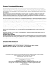
This equipment stays pressurized until pressure is
manually relieved. To help prevent serious injury from
pressurized fluid, such as skin injection, splashing
fluid and moving parts, follow the Pressure Relief
Procedure when you stop spraying and before
cleaning, checking, or servicing the equipment.
FIG. 1
5
11
7
Torque 90 – 110 ft. lbs.
Yoke
Rod Guide