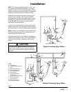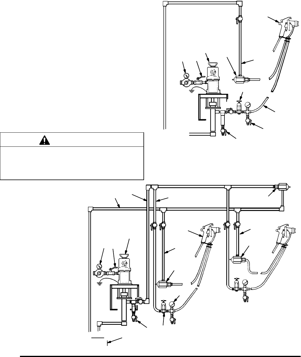
Fig. 1
KEY
A Air Regulator
B Bleed-Type Master Air Valve
C Pump
D Fluid Filter & Drain Valve
E Main Fluid Supply Line
F Gun Fluid Supply Line
G Fluid Regulator
H Fluid Pressure Gauge
& Drain Valve
J Air-Assisted Airless Spray Gun
K Back Pressure Valve
L Fluid Return Line
M Main Circulating Line
N Fluid Supply Container
AB
C
D
E
F
J
K
M
H
K
L
C
J
Single Circulating Spray Station
Multiple Circulating Spray Station
G
N
F
K
L
A
B
D
G
H
K
L
3307892
Installation
NOTE: The Typical Installations shown in Fig. 1 are
only guides for selecting and installing a circulating
system. Contact your Graco representative or Graco
Technical Assistance (see back page) for assistance in
designing a system to meet your particular needs.
Install the back pressure valve (K) in the spray gun
return line (L) as shown in the Typical Installation
drawing below or at right. Using pipe sealant on pipe
threads, connect the lines to the 3/8 npt(f) inlet and
outlet. Be sure the flow direction agrees with the
markings on the valve housing.
If more than one spray station is used, install a back
pressure valve (K) in the circulating line (M), after the
last spray station to maintain proper system pressures.
NOTE: The two 1/4–20 tapped mounting holes on the
side of the valve housing are for mounting the valve
when flexible fluid lines are used.
The back pressure valve was tested in lightweight oil.
Flush the entire system with a solvent compatible with
the fluid being sprayed or dispensed, then test the
system.
CAUTION
The new system must be cleaned and tested thor-
oughly before admitting fluid to the back pressure
valve, to avoid contaminants clogging or damaging
the valve.


