


310564 7
Setup
WARNING
To reduce the risk of serious injury whenever you
are instructed to relieve pressure, always follow the
Pressure Relief Procedure on page 10.
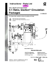
Wall Mount installation of the Circulation
Package
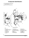
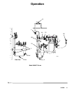
Fig. 1. The circulation package consists of the pump
mounted on the wall mount frame. Also on the wall
mount frame are air filter, master air valve, air controls,
lubricator, surge tank, fluid filter, and plumbing.
NOTE: Ensure that there is 5 ft (1.5 m) overhead
clearance for a wall mounted system.
NOTE: Refer to Fig. 1, and to the Dimension drawing
on page 28 and the Mounting Hole Layout on page 29.
1. Relieve system pressure prior to installation of
circulation package. Follow Pressure Relief
Procedure on page 10.
2. Ensure that wall is strong enough to support
weight of circulation package, accessories, fluid
plumbing, and stress caused during pump opera-
tion.
3. Using capable hoist, position wall mount frame (R)
so that the top edge is 5 to 6 ft (1.5 to 1.8 m)
above floor. Check that wall mount frame is level.
Mark four holes on wall for each of four wall mount
feet.
4. Drill holes where marked on wall.
WARNING
The wall mount frame (R) must be bolted to the
wall. Do not simply hang the wall mount frame.
Failure to do so may cause circulation package to
fall causing equipment damage or personal injury.
5. Using capable hoist, lift circulation package back
into position. Bolt wall mount frame (R) to wall.
Use 1/2 in. bolts and washers to mount circulation
package to wall. Use bolts that are long enough to
keep wall mount frame from vibrating during
operation.
Single or Dual Floor Mount installation of
the Circulation Package
Fig. 1. The circulation package consists of the pump
mounted on the wall mount frame. Also on the wall
mount frame are air filter, master air valve, air controls,
lubricator, surge tank, fluid filter, and plumbing.
NOTE: Ensure that there is 7 ft (2.1 m) overhead
clearance for a floor mounted system.
NOTE: Refer to Fig. 1, and to the Single Mount Floor
Stand drawing on page 24 or the Dual Mount Floor
Stand drawing on page 25. Also refer to the Mounting
Hole Layouts on page 29.
1. Relieve system pressure prior to installation of
circulation package. Follow Pressure Relief
Procedure on page 10.
2. Anchor either single or dual floor stand to floor
using 1/2 in. bolts.
WARNING
Do not attempt to mount two circulation packages
on a single mount floor stand. Use dual mount
stand for dual or back–to–back installations. Failure
to do so can result in mount failure causing equip-
ment damage or personal injury
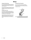
3. Using capable hoist, position wall mount frame (R)
so that the top edge is level with the top edge of
the floor stand. For dual, use second hoist and
align with dual floor stand and first circulation
package.
4. Bolt single unit or dual units to floor stand using
3/8 in. hardware.