


307004Gą7
Service
NOTE:
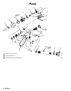
The numbers in parentheses in the text refer to
reference numbers in the parts drawing on page 8.
NOTE:
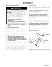
Periodically inspect the vent in the gun handle
for build-up of fluid, which could indicate an internal
leak. See Fig. 1. Service the valve needle and packing
as needed.
Valve Seat and Needle Replacement
WARNING
To
reduce the risk of serious injury whenever you
are instructed to relieve pressure, always follow the
Pressure Relief Procedure
on page 5.
If fluid continues to flow after the trigger is released,
the gun valve may be obstructed or need adjustment.
The valve stem (3) or valve seat (2) may be worn or
damaged.
Adjusting the Valve
1.
Relieve the pressure.
2.
Squeeze the gun trigger
. Remove the valve seat
(2). Let the spring (8) push the valve stem (3)
forward, and then loosen the nut (4).
3.
Remove the actuating pin (24), then turn the
adjusting nut (21) out a couple of turns.
4.
Reassemble the gun and check the free travel of
the trigger
. It should be approximately 3/16 inch
(3.18 mm). See Fig. 1.
5.
Repeat the procedure turning the adjusting nut as
needed, until the correct free travel is obtained.
Adjusting the Spring Tension
1.
Relieve the pressure.
2. T
urn the spring tension adjusting screw (19) so the
spring (8) is completely compressed when the
trigger (17) is squeezed in all the way
.
Inspecting the V
alve for Obstruction or Damage
1.
Relieve the pressure.
2.
Disconnect the gun from the hose.
3.
Disassemble the gun, then clean and inspect the
parts.
CAUTION
Be sure to squeeze the trigger when removing the
valve seat (2). Handle the valve seat (2) and valve
stem (3) carefully to avoid damaging the hard car
-
bide portion of these parts.
4.
Replace any worn or damaged parts and reas
-
semble the gun. Adjust the free travel of the trigger
as instructed in
Adjusting the Valve
,
at left.
LUBRICA
TION NOTE:
Apply thread lubricant when
installing the valve seat (2), adjusting screw (19), or
tube (20).
T
ORQUE NOTE:
When assembling the valve seat (2),
packing housing (23), or tube (20) to the gun body
(14), torque them to 100 in-lb (1
1 N
Sm).
Valve Needle and Packing Service
WARNING
To
reduce the risk of serious injury whenever you
are instructed to relieve pressure, always follow the
Pressure Relief Procedure
on page 5.
If fluid leaks past the v-block packing (7), the packing
housing (23) may be loose, or the v-block packing or
valve stem (3) may be worn or damaged. T
ighten the
packing housing. If it still leaks,
relieve the pressure
and disconnect the hose from the gun. Disassemble
the gun and replace the v-block packing. When reas
-
sembling, lubricate the v-block packing (7) and spring
(8) with general purpose grease.
CAUTION
When tightening the bushing (22),
be sure
to grip
the gun body (14),
not
the handle (15). This reduces
the chance of loosening the connections and damag
-
ing the gun.