


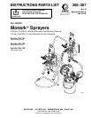
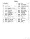
5308–367
Installation
Be sure that all operators read and understand this
entire manual and the separate manuals supplied with
components and accessories before using this equip
-
ment.
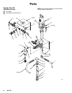
Reference numbers and letters in parentheses refer to
the figures and parts drawings.
Accessories mentioned are available from your Graco
distributor
. If you supply your own accessories, be sure
they area adequately sized to meet your system’
s
requirements.
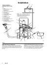
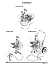
The T
ypical Installation shown in Fig. 4 is only an
example. For assistance in designing a system to meet
your particular needs, contact your Graco distributor
.
System Accessories
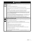
WARNING
Two
required components are supplied with your
pump, to help reduce the risk of serious injury
including fluid injection, splashing in the eyes or on
the skin, or injury from moving parts if you are
adjusting or repairing the pump.
The
bleed-type master air valve (B)
relieves air
trapped between this valve and the pump. T
rapped
air can cause the pump to cycle unexpectedly
.
To
bleed air from the pump, the pump air regulator
(F) must be open when you close this valve.
The
fluid drain valve (H)
assists in relieving fluid
pressure in the displacement pump, hose, and gun;
triggering the gun to relieve pressure may not be
sufficient.
Install an air line filter (E) in the main air line, to re
-
move harmful dirt and moisture from the compressed
air supply
. T
o provide automatic lubrication of the air
motor
, install an air line lubricator (P) downstream from
the pump air regulator (F). Install a second master air
valve (D) in the main air line, to isolate the accessories
for servicing.
Grounding
T
o reduce the risk of static sparking, ground the pump,
object being sprayed, and all other spray equipment
used or located in the spray area. Check you local
electrical code for detailed grounding instructions for
your area and type of equipment. Be sure to ground all
of this spray equipment.
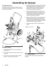
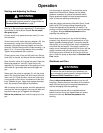
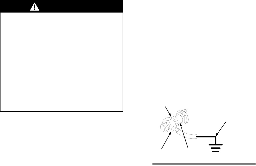
1.
Pump:
loosen the grounding lug locknut (W) and
washer (X). Insert one end of a 1.5 mm
2
(12 ga)
minimum ground wire (Y) into the slot in lug (Z)
and tighten the locknut securely
. See Fig. 3. Con
-
nect the other end of the ground wire to a true
earth ground.
2.
Air hoses:
use only grounded air hoses.
3.
Fluid hoses:
use only grounded fluid hoses.
4.
Air compressor:
follow manufacturer
’
s recommen
-
dations.
5.
Spray gun:
grounding is obtained through connec
-
tion to a properly grounded fluid hose and pump.
6.
Fluid supply container:
according to your local
code.
7.
Object being sprayed:
according to your local
code.
8.
All solvent pails used when flushing,
according to
local code. Use only metal pails, which are con
-
ductive, placed on a grounded surface. Do not
place the pail on a non-conductive surface, such
as paper or cardboard, which interrupts the
grounding continuity
.
9.
T
o maintain grounding continuity when flushing or
relieving pressure
, always hold a metal part of the
spray gun firmly to the side of a grounded metal
pail, then trigger the spray gun.
Fig. 3
W
X
Y
Z
0864