


5
308-460
Setup
CAUTION
This equipment is compatible with most water
based materials. See the wetted parts in the
Tech-
nical Data
section and your fluid and solvent
manufacturer’
s compatibility information.
I. Prepare the operator.
All
persons who operate the system should be trained
in the safe, efficient operation of all system compo
-
nents as well as the proper handling of the chemical
coating. At a minimum, all operators should
thoroughly read the safety
, installation and operation
sections of this manual and the component manuals.
II. Prepare the site.
1. Use
a minimum recommended 5
HP (3.7
kW) air
compressor for ef
ficient operation.
2.
Clear obstacles and debris that could hinder the
operator’
s movement.
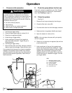
3.
Bring an air line from your compressed air supply
to the pump location. Be sure the air is dry and
filtered. Install a bleed–type master air valve (A)
upstream from the pump. Another master air valve
(14) is supplied with the package. When the
bleed–type master air valve is closed and the
pump air regulator (8a) is opened, the valve
relieves all air pressure to the system.
4.
Have a grounded metal waste pail available to use
when draining the fluid filter
.
5. V
entilate the spray booth.
WARNING
T
o prevent hazardous concentrations of toxic and/
or flammable vapors, spray only in a properly venti
-
lated spray booth.
Never operate the spray gun
unless ventilation fans are operating.
Check and follow all of the national, state and local
codes
regarding air exhaust velocity requirements.
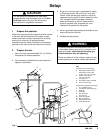
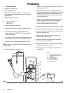
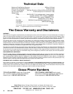
Fig. 1
04098
KEY
Components
you must supply:
A
Bleed-type master air valve
Required for pump; order
part no. 107–142, 1/4” npt(f)
B
Air filter
. Order part no.
106–149, 1/2 npt(f)
C
Air supply line
D
Grounded 5 gallon metal pail
E
Air line moisture trap
Components supplied with package:
1
30:1 President
pump
3
Air-assisted airless spray gun
4
Spray tip
5
Fluid filter
6
Gun fluid hose
7
Gun air hose
8a
Pump air regulator
8b
Gun air regulator
14
Bleed–type air valve
30
Pump ground wire
7
6
3,4
A
B
E
D
1
30
8b
8a
14
5
C