


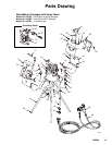

14 308846
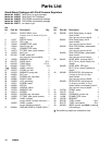
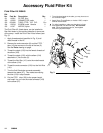
Accessory Fluid Filter Kit
Fluid Filter Kit 240440
Ref.
No. Part No. Description Qty.
101 114361 FILTER, fluid 1
102 113322 CONNECTOR, male 1
103 054188 TUBE; PTFE;R3/8” O.D. 8 in.
104 113534 ELBOW, male x female 2
105 111917 NIPPLE; Nylon 1
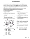
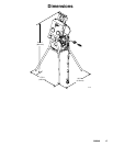
The Fluid Filter Kit, listed above, can be installed to
filter fluid drawn by the suction tube after it comes out
of the pump. Install the Fluid Filter Kit as follows (see
Fig. 3):
1. Apply thread sealant (specified in Fig. 3) to all
male threads in this kit.
2. Remove the male connector (6) and the PTFE R
tube (18) that connect to the top of the tee (5).
See the Parts drawing on page .
3. Thread the nipple (105) into the female threads of
the elbow (104).
4. Thread the nipple (105), with the elbow (104)
attached to it, into the tee (5).
5. Thread the fluid filter (101) onto the male threads
of the elbow (104).
6. Thread the male connector (102) into the fluid filter
(101).
7. Turn the fluid filter/male connector assembly
towards the elbow (27). This makes connecting
the tube (103) in step 8 easier.
8. Cut the PTFERtube (103) to the proper length,
and install it to run from the male connector (102)
to the elbow (27).
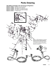
Fig. 3
102}
103{
104}
105}
{ To avoid sharp bends in the tube, you may have to cut
it to a shorter length.
} Apply Graco Thread Sealer, or LoctiteR 567, or equiv-
alent to male threads.
5
27
103}
8114A
101Y
Y For initial installation, make sure the dome is firmly
hand tightened onto the filter body. Do not use a
tool. During subsequent service, hand tighten
more firmly to prevent drips.