


11308876
Service
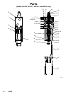
(Models 965766, 965767, 965768, and 965786 only)
WARNING
To reduce the risk of serious injury
whenever you are instructed to relieve
pressure, always follow the Pressure
Relief Procedure on page 8.
SKIN INJECTION HAZARD
Disassembly
1. Relieve all air and fluid pressure.
2. Disconnect the valve from the system.
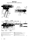
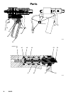
3. Remove the four nosepiece screws (15), and pull
the nosepiece (40) away from the valve. Remove
the snuff-back ring (41). See Fig. 5, page 14.
4. Use an 1/8 in. pin punch in the needle hole (A) to
unscrew the needle (27). If the shaft (3) spins,
insert a dowel pin in the shaft hole (B) to hold it
steady, then unscrew the needle (27).
5. Remove the seat (25), gasket (38), and o-ring
(39).
6. Remove the two fluid housing screws (23) and
remove the fluid housing (26). Remove the primary
fluid seal (22) from the fluid housing (26).
7. Pull the bearing/lube housing (19) from the air
cylinder (1). Remove the bearing (21), bearing
o-ring (16), and secondary fluid seal (20). Remove
the grease fittings (18).
8. Remove the C-clip (12) from the back of the air
cylinder (1). Push the shaft (3) into the air cylinder
to dislodge the air cylinder cap (11). Remove the
cap o-ring.
9. Remove the internal C-clip (12). Push the shaft (3)
to dislodge the piston (10) assembly from the air
cylinder (1).
10. Remove the adjustment nut (44) from the shaft (3).
11. Remove the adjustment shaft (42) from the shaft
(3).
12. Remove the pin (7), o-ring (9), and piston o-ring
(6).
13. Use a 1/4 in. pin punch to knock out the bearings
(5) and o-rings (4).
Air Switch Handle (if equipped)
1. Remove the trigger (56).
2. Loosen the set screw above the trigger safety. Pull
off the handle (55).
3. Remove the four retaining screws (60). Pull the
housing (50) and gasket (30) away from the air
cylinder (1).
Air Valve
1. Unscrew the stem guide (58).
2. Remove the trigger pin (59), o-ring (57), spool
(49), spacers (51, 52), o-rings (46, 48) and spring
(47).
3. Remove the bushing (53) from the housing (50)
with the screw (54).
4. Remove the screws (60) and lock-washers (61)
from the air cylinder (1).
Electric Switch Handle (if equipped)
1. Disconnect the power from the gun.
2. The switch, housing, and cable are not repairable.
Replace these parts as a complete assembly.
3. Remove the trigger (56).
4. Loosen the setscrew above the trigger safety. Pull
off the handle (55).
5. Remove the four manifold retaining screws (60).
Pull the housing (50) and gasket (30) away from
the air cylinder (1).
6. Remove the bushing (53) from the housing (50)
with the screw (54).
7. Remove the screws (60) and lock-washers (61)
from the air cylinder (1).