


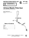

307-6557
Operation
Spraying
WARNING
RECOIL
HAZARD
Due to the very high pressure fluid
emitted, a strong recoil action will occur
when you open the ON/OFF lever on
this gun. If you are unprepared, your hand could be
forced back toward your body or you could lose
your balance and fall, resulting in serious injury
.
Grasp the gun grip firmly with one hand, be sure
you have good footing, before opening the ON/
OFF lever with your other hand.
WARNING
INJECTION HAZARD
T
o reduce the risk of a fluid injection
injury
, follow the
Pressure Relief Proce
-
dure
on page 6 before removing or
installing a spray tip and whenever you are
instructed to relieve pressure.
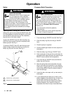
1.
Before starting the pump, be sure the ON/OFF
lever is closed. See Fig. 2.
2. T
urn on the air to the pump to the minimum air
pressure needed.
3.
Hold a metal part of the pole gun firmly to the side
of the metal supply drum, with the nozzle pointed
into the drum.
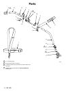
4.
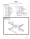
Grasp the gun grip (9–see Fig. 1, page 4) firmly
with one hand. Be sure you have good footing,
then open the ON/OFF lever with your other hand.
5.
Operate the pump slowly until the entire system is
primed and all air has been pushed out of the
pump and hoses.
6.
Close the ON/OFF lever and follow the
Pressure
Relief Procedure
on page 6.
7.
With the pressure fully relieved, install the spray tip
and tip guard. See the chart to the right to select
an appropriate spray tip.
CAUTION
T
o reduce the risk of damage to the tip guard, never
hang the gun by the tip guard. Any damage to the
sharp edges of the openings in the tip guard will
cause paint to collect at that area.
Spray Tip Selection Chart
Orifice
Size
Tip
Size
Fan
Pattern at
12
in. (305 mm)
Part No.
Use T
ip
Guard
0.072 in.
(1.83 mm)
flat
14–16 in.
(356–406 mm)
180–727 220–222*
0.062 in.
(1.57 mm)
flat
14–16 in.
(356–406 mm)
160–950 220–222*
0.052 in.
(1.32 mm)
flat
14–16 in.
(356–406 mm)
164–438 220–222*
0.053 in.
(1.35 mm)
ball
14–16 in.
(356–406 mm)
205–746 205–649**
0.063 in.
(1.60 mm)
ball
14–16 in.
(356–406 mm)
205–976 205–649**
0.071 in.
(1.80 mm)
ball
12–14 in.
(305–356 mm)
207–017 205–649**
*
Supplied with the mastic flow control.
.
** Reverse-A-Clean
I
T
ip Guard Kit must be purchased
separately.
Service
WARNING
INJECTION
HAZARD
T
o reduce the risk of a fluid injection
injury
, follow the
Pressure Relief Proce
-
dure
on page 6 before checking or
servicing any of the system equipment and when
-
ever you are instructed to relieve pressure.
Repair Kit 218–692 is available for repairing part no.
181–253 Ball V
alve. See page 9.