


30887010
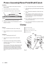
Pinion Assembly/Rotor/Field/Shaft/Clutch
Installation
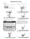
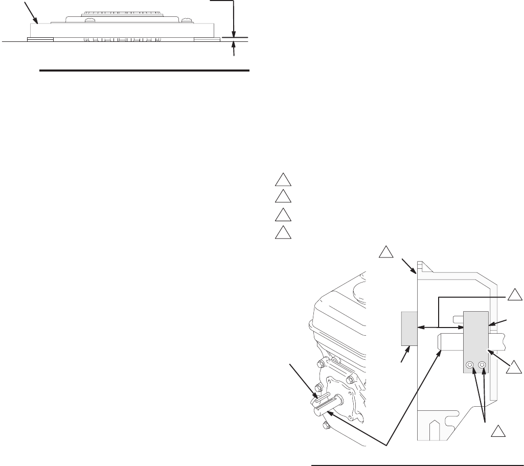
1. Fig. 10. Lay two stacks of two dimes on smooth
bench surface.
2. Lay armature (4a) on two stacks of dimes.
3. Press center of clutch down on bench surface.
Fig. 10
4a
8705A
0.12 ±.01 in. (3.0 ±.25 mm)
4. Install armature (4a) on engine drive shaft.
5. Install four screws (16) and lockwashers (17) with
torque of 125 in-lb.
6. Fig. 8. Tap pinion shaft (19d) in with plastic mallet.
7. Install retaining ring (19e) with beveled side facing
field (Y).
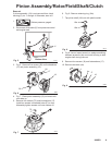
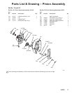
8. Fig. 7. Place pinion assembly on bench with rotor
side up.
9. Apply locktite to screws. Install four screws (16)
and lockwashers (17). Alternately torque screws
to 125 in-lb until rotor is secure. Use threaded
holes to hold rotor.
10. Fig. 6. Install pinion assembly (19) with five screws
(10) and lockwashers (9).
11. Fig. 5. Connect field cable (X) to pressure control
and engine lead.
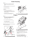
Clamp
Removal
1. Fig. 11. Loosen two screws (16) on clamp (8),
2. Push screwdriver into slot in clamp (8) and remove
clamp.
Installation
1. Fig. 11. Install engine shaft key (7).
2. Tap clamp (8) on engine shaft (A) with plastic
mallet.
3. Press clamp (8) onto engine shaft (A). Maintain
dimension shown note 2 in Fig. 11. Chamfer side
must face engine.
Check dimension: Place rigid, straight steel bar (B)
across face of clutch housing (5). Use accurate
measuring device to measure distance between
bar and face of clamp. Adjust clamp as necessary.
Torque two screws (16) to 125 ±10 in-lb (14 ±1.1
Nm).
Fig. 11
16
5
B
03483
1
3
2
Face of clutch housing
1.812 ±.010 in. (46.02 ±.25 mm)
Torque to 125 ±.10 in-lb (14 ±1.1 Nm)
1
2
3
7
8
A
4
Chamfer this side
4