


17308972
Displacement Pump Service
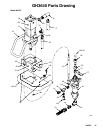
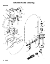
237510 and 222801 Displacement Pumps
Disconnecting the Displacement Pump
1. Flush the pump, if possible. Stop the pump at the
bottom of its stroke.
WARNING
To reduce the risk of serious injury whenever you
are instructed to relieve pressure, always follow the
Pressure Relief Procedure on page 10.
2. Relieve the pressure.
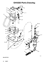
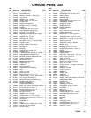
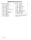
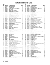
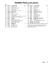
3. Reference Roof Rig Parts Drawings, pages 18
through 27.
4. Disconnect the air or hydraulic hose and the fluid
hose. Plug all hydraulic hoses immediately, to
prevent contamination of the hydraulic system.
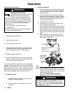
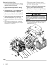
5. Disconnect the displacement pump (46) from the
motor (29) as follows. Note the relative position of
the pump fluid outlet (81) to the hydraulic inlet (76)
of the motor. If the motor does not require servic-
ing, leave it attached to its mounting.
C
A
UTION
Use at least two people when lifting, moving, or dis-
connecting the pump. This pump is too heavy for one
person. Support the displacement pump while it is
being disconnected, to prevent it from falling and
causing injury or property damage.
If the pump is mounted on a cart, slowly tip the cart
backward until the handle rests on the ground, then
disconnect the displacement pump.
6. Using an adjustable wrench (or hammer and
punch), unscrew the coupling nut (170) from the
moto r shaft ( Ref. 29). Take care not to lose or
drop the coupling collars (80).
7. Hold the tie rod flats with a wrench to keep the
rods from turn ing. Unscrew the nuts (48) from the
tie rods (47). Carefully remove the displacement
pump (46) from the motor (29).
8. Refer to separate manual listed in parts list for
displacement pump servi ce. To service the hydrau-
lic motor, refer to the separate motor manual,
supplied.
Reconnecting the Displacement Pump
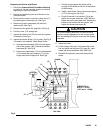
1. Make su re coupling nut (170) and coupling collars
(80) are in p lace on displacement rod (Ref. 29).
2. Use at least two people to hold the displacement
pump while another reconnects it to the motor (see
the preceding CAUTION). Orient the pump fluid
outlet (81) to the hydraulic inlet (76) as was noted
in step 5 under Disconnecting the Displacement
Pump. Position the displacement pump (46) on
the tie rods (47).
3. Screw the nuts (48) onto the tie rods (47) and
torque to 81--89 N.m (60--66 ft-lb).
4. Scre w coupling nut onto motor shaft (Ref. 29),
loosely. Hold the motor shaft flats with a wrench to
keep it from turning. Use an adjustable wrench to
tighten the coupling nut. Torque to 196--210 N.m
(145--155 ft-lb).
5. Reconnect all hoses. Reconnect the ground wire i f
it was disconnected. Fill the packing nut (2) 1/3 full
of Graco Throat Seal Liquid or compatible solvent.
6. T urn on the hydraulic power supply. Open the
hydraulic return line valve first, then the supply line
valve. Run the pump slowly to ensure proper
operation.
WARNING
To reduce the risk of serious injury whenever you
are instructed to relieve pressure, always follow the
Pressure Relief Procedure on page 10.
7. Before returning the pump to production, relieve
the pressure and retorque the packing nut (2) to
136--149 N.m (100--11 0 ft-lb).