


12 308876
Service
(Models 965766, 965767, 965768, and 965786 only)
Reassembly
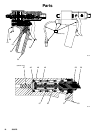
Air Cylinder Section
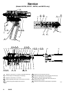
1. Lubricate the shaft o-rings (4) and the bearings (5)
with grease supplied in the repair kit. Insert o-rings
into the air cylinder (1) and air cap (11) cavities.
See Fig. 5.
2. Press the bearings (5) flush into the air cylinder
housing and air cap, trapping the o-rings (4).
3. Lubricate and reassemble the piston assembly;
piston (10), o-ring (9), dowel pin (7), adjustment
shaft (42), o-ring (6), and shaft (3). Use Loctiter
Primer N7649 and Loctiter TL242, 243, or
equivalent (“blue” Loctite) when assembling the
adjustment shaft (42). Tighten the shaft to 15–20
in–lb (1.7–2.2 NSm). The shaft (3) should hang
with some play to be self-aligning in the bearing.
4. Lubricate the air cylinder (1) ID with the grease
supplied. Push the piston (10) assembly into the
air cylinder.
5. Orient the air inlet manifold (2) (if used) as shown.
Match the gasket openings to the air ports.
Fluid Section
1. Lubricate the bearing (21), o-ring (16) and cup seal
(20). Put the o-ring (16) on the bearing. Carefully
insert the seal (20) into the bearing recess, with
the lips of the o-ring facing into the bearing. Be
careful not to damage the seal lips.
2. Push the bearing (21) seal end first into the
housing (19). Be sure that the grease hole in the
side of the bearing lines up with the grease ports in
the housing (19).
3. Holding the bearing (21) in place, push the bearing
assembly over the shaft (3).
4. Lubricate the main fluid seal (22) and its cavity in
the housing (26). Carefully press the seal, lip-first,
into the housing.
5. Push the housing (26) and seal (22) over the shaft
(3) and up against the bearing housing.
6. Apply anti–seize lubricant (Loctite 56765 or
equivalent) to the fluid housing screws (23) and
loosely install the screws to retain the housings.
Do not tighten the screws yet.
7. Insert the gasket (38) and seat (25). These items
are reversible and can be installed in either
direction.
8. Use Loctite Primer N7649 and Loctite TL242, 243,
or equivalent (“blue” Loctite) when assembling the
needle (27) and tighten to 15–20 in–lb (1.7–2.2
NSm).
9. Apply air pressure to the CLOSE port, or to the
pneumatic trigger valve if installed. This will align
the shaft, seal, and bearing. Tighten the fluid
housing screws (23) oppositely and evenly to
40–45 in-lbs (4.5–5 NSm).
10. Install the nosepiece (40) with the PTFE o-ring
(39), screw (15), and snuff-back ring (41), if used.
The snuff-back ring has an internal bevel on one
end which faces into the nosepiece. Tighten the
nosepiece screws to 15–20 in-lbs (1.7–2.2 NSm).