


6 308981
Installation
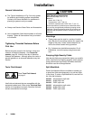
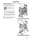
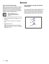
Fluid Pressure Relief Valve
CAUTION
Some systems may require installation of a pressure
relief valve at the pump outlet to prevent overpres-
surization and rupture of the pump or hose.
See Fig. 1.
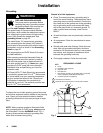
Thermal expansion of fluid in the outlet line can
cause overpressurization. This can occur when using
long fluid lines exposed to sunlight or ambient heat,
or when pumping from a cool to a warm area (for
example, from an underground tank).
Overpressurization can also occur if the Husky pump
is being used to feed fluid to a piston pump, and the
intake valve of the piston pump does not close,
causing fluid to back up in the outlet line.
Fig. 1
1
2
Connect fluid inlet line here.
Install valve between fluid inlet and outlet ports.
1
2
Connect fluid outlet line here.
3
3
9073A
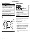
Air Exhaust Ventilation
Read Toxic Fluid Hazard on
page 3.
Read Fire and Explosion
Hazard on page 3.
Be sure the system is properly ventilated for your
type of installation. You must vent the exhaust to a
safe place, away from people, animals, food handl-
ing areas, and all sources of ignition when pumping
flammable or hazardous fluids.
Diaphragm failure will cause the fluid being pumped
to exhaust with the air. Place an appropriate con-
tainer at the end of the air exhaust line to catch the
fluid. See Fig. 2 .
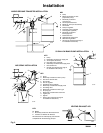
The air exhaust port is 3/8 npt(f). Do not restrict the air
exhaust port. Excessive exhaust restriction can cause
erratic pump operation.
See Venting Exhaust Air in Fig. 2. Exhaust to a
remote location as follows:
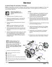
1. Remove the muffler (W) from the pump air exhaust
port.
2. Install an electrically conductive air exhaust hose
(X) and connect the muffler to the other end of the
hose. The minimum size for the air exhaust hose
is 3/8 in. (10 mm) ID. If a hose longer than 15 ft
(4.57 m) is required, use a larger diameter hose.
Avoid sharp bends or kinks in the hose.
3. Place a container (Z) at the end of the air exhaust
line to catch fluid in case a diaphragm ruptures.
See Fig. 2.