


16 308981
Service
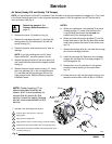
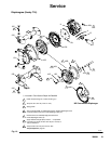
Diaphragms (Husky 515)
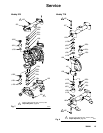
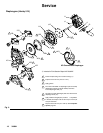
NOTE: Fluid Section Repair Kit D05XXX is available. See page 22 to order the correct kit for your pump. Parts
included in the kit are marked with a double dagger (}) in Fig. 9 and in the Parts Drawings and Lists. General
purpose grease 111920 and Adhesive 113500 are supplied in the kit. Service the diaphragms as follows. See Fig. 9.
Disassembly
1. Relieve the pressure. See
Pressure Relief Procedure on
page 10.
2. Remove manifolds (102 and 103) and fluid cov-
ers (101).
NOTE: Make sure all the check valve parts stay in
place. See Fig. 7 on page 15.
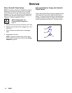
3. Remove one of the fluid-side diaphragm plates
(105) (whichever one comes loose first when you
use a wrench on the hex of each), and pull the
diaphragm shaft out of the center housing (11).
Overmolded Diaphragms: The air cover bolts
may make it difficult to remove the overmolded
diaphragms on the 515 pump. Use a flat surface
that fits within the bolt pattern to apply pressure on
one of the diaphragms to shift the diaphragm shaft
to one side. Apply pressure until the other dia-
phragm is separated from the air cover. Rotate the
separated diaphragm counterclockwise until the
diaphragm assembly comes free. Pull the second
diaphragm assembly and the diaphragm shaft (15)
out of the center housing. (11)
4. Use a wrench on the flats of the diaphragm shaft
(15) to remove the other fluid-side diaphragm plate
(105) from the diaphragm shaft.
Overmolded Diaphragms: Use a wrench on the
flats of the diaphragm shaft (15) to remove the
second diaphragm.
5. Remove the screws (106), remove the left (114)
and right (113) air covers, and remove all old
gasket (12) material from the ends of the center
housing (11) and the surfaces of the air covers.
6. Remove the diaphragm shaft u-cups (416) and
pilot pin o-rings (1).
7. Inspect all parts for wear or damage, and replace
as necessary.
Reassembly
1. Insert a diaphragm shaft u-cup (416) and a pilot
pin o-ring (1) into the bores of the center housing
(11).
NOTE: Make sure the lips of the u-cup face out of
the center housing.
2. Line up the holes in the gasket (12) with the holes
in the end of the center housing (11), and use six
screws (106) to fasten an air cover (113 or 114) to
the end of the center housing (11). Torque the
screws to 35 to 45 in-lb (4.0 to 5.1 N-m).
3. Position the exhaust cover (13) and o-ring (4) on
the center housing (11).
4. Repeat steps 1 and 2 for the other end of the
center housing and the remaining air cover.
5. Apply medium-strength (blue) Loctite or equivalent
to the threads of the fluid-side diaphragm plates
(105). Install on one end of the diaphragm shaft
(15) the following parts (see proper order in Fig. 9):
air-side diaphragm plate (6), backup diaphragm
(402, used only on models with PTFE dia-
phragms), diaphragm (401), and fluid-side dia-
phragm plate (105).
NOTE: The words “AIR SIDE” on the diaphragm
(401), the backup diaphragm (402, used only on
models with PTFE diaphragms) and the flat side of
the air-side diaphragm plate (6) must face toward
the diaphragm shaft (15).
Overmolded Diaphragms: Assemble the air–side
plate (6) onto the diaphragm (401). The words AIR
SIDE on the air–side plate must face away from
the diaphragm. Apply medium–strength (blue)
thread locking adhesive to the threads of the
diaphragm assembly. Screw the assembly into the
diaphragm shaft (15) hand tight.