


7GC-1387H
Hose Attachment
1. Push in and rotate the trigger lock to stop the trigger
from being activated.
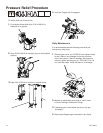
2. Attach the (black p/n 21694-25) material hose to
the material inlet tting on the back of the gun.
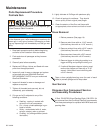
3. Attach the (yellow p/n 236) solvent line to the solvent
inlet tting on the back of the gun.
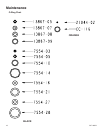
4. Attach the (stainless steel p/n 20190-00) catalyst
hose to the catalyst inlet tting on the back of the
gun.
5. Attach the (Clear) trigger air tubing to the
trigger air inlet tting on the back of the gun.
6. If the optional berglass roving chopper is being used,
attach the “red” chopper air line to the chopper air
inlet tting on the back of the gun.
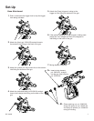
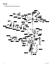
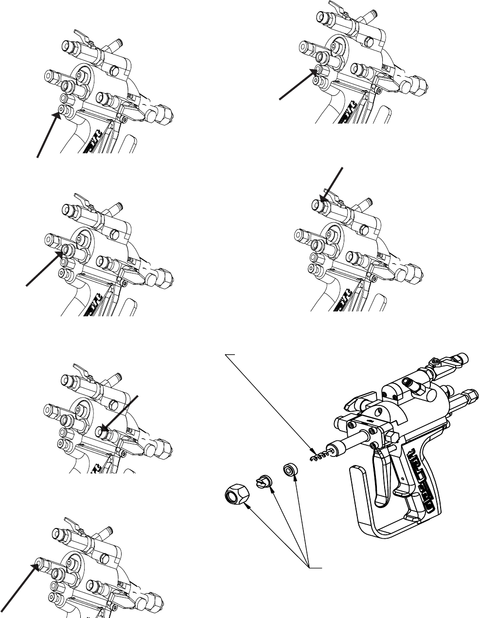
7. Mixing element assembly
Set-Up
A - Insert mixing element,
p/n: 20634-01, straight
into the gun front housing,
p/n: 23760-00
B - Place retaining nut, p/n: 23002-00
along with spray tip, p/n: 23005-XX
and spray tip spacer, p/n: 23046-00
onto gun housing.