


15308972
Replacing the Cooler and Blower
1. Follow the Pressure Relief Procedure W arning
on page 10. Let the hydraulic system cool before
beginning the service procedure.
2. Remove the hydraulic pump as instructed in the
previous section.
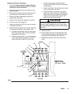
3. Disconnect the cooler to reservoir return hose (7.)
by loosening the hose clamp (8). See Fig 8.
4. Remove the cooler capscrews (49) and lock-
washers (66). See Fig 8.
5. Remove the fan guard (23, page 36). See Fig 8 .
6. Pull the cooler (115) straight out.
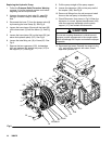
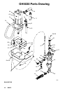
7. Inspect the rubber pad (116) fo r wear and replace
if necessary. See Fig 9.
8. Inspect the blower wheel (114) for w ear. See Fig 8.
If it needs to be replaced, follow Steps 8a--8e.
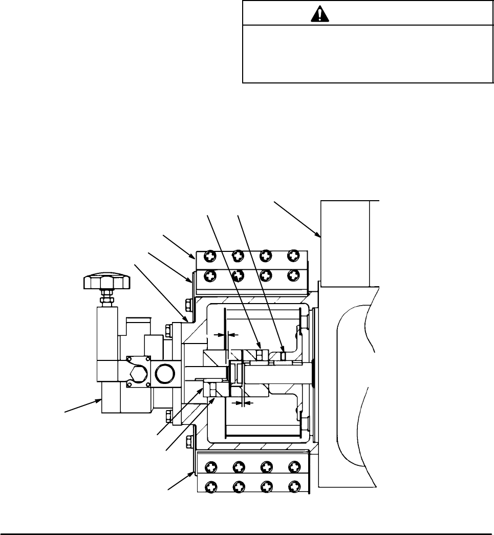
a. Unscrew the setscrews (108) from the engine
half of the coupler (109). Unscrew the blower
setscrews (B). See Fig 9.
b. Remove the capscrews (112) and lockwashers
(113) holding the pump support (117) to the
engine and pull the support off. See Fig 8.
c. Pull the pump support and blower off far
enough for the blower to fall out of the bottom
of the housing.
d. Install a new blower. Secure the pump support
(117) to the engine. See Fig 8.
e. Check Dimension A as shown in Fig 9 and
tighten the coupler setscrews (108). Butt the
blower hub up to the coupler half, keeping the
blower in full contact with the coupler , and
tighten the blower setscrews (B).
C
A
UTION
The correct coupling dimension is critical to avoid
improper coupler engagement to the coupler spider
which will damage the coupler and make the sprayer
inoperable.
9. Install the cooler.
10. Fold the flaps of the pad (116) toward the cooler
fins and install the fan guard (23, page 36), caps-
crews (49) and lockwashers (66). See Fig 8.
11. Reinstall the hyd raulic pump and reconnect all
hoses.
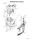
A
116
108
109
107
117
23
115
108
ENGINE
DIMENSION A
0.05 in. ± 0.010
(1.27 mm ± --0. 254)
TOP VIEW
A
Fig 9
B