


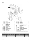

Component Identification
2 313754C
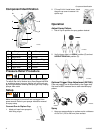
Component Identification
Pressure Relief Procedure
The spray gun cup is pressurized by the gun air supply.
To reduce the risk of serious injury from pressurized fluid
or accidental spray from gun, always turn off the air sup-
ply to the gun before removing the spray gun cup. Unplug
sprayer from outlet
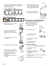
Setup
Make sure sprayer is turned off and unplugged from
power source. Refer to your sprayer instruction manual
for spray setup.
Connect Gun to Siphon Cup
1. Attach air hose from sprayer to
inlet fitting of gun.
2. Fill cup 3/4 full. Install cover. Latch
the gun cup cover to secure it to
siphon cup.
Operation
Adjust Spray Pattern
1. Set air cap to position for spray pattern desired.
2. Verify trigger slide is in SPRAY position (E) and not
NEEDLE REMOVAL position (D).
Optional Trigger Stop Adjustment (257086)
Flow and pattern size is determined by the trigger stop.
Set knob to OFF. Increase flow to attain desired spray
pattern.
Spray
1. Keep gun perpendicular to surface and at a distance
of 6 to 8 in. (150 to 200 mm) from surface.
ID Component ID Component
A Siphon Cup
B Check Valve H Air Inlet
C Air Cap J
EasyGlide
™
Trigger
D Air Nozzle K Latch
E Fluid Needle M Swivel Tube
G Trigger Slide N Strainer
A
B
C
D
E
H
J
K
M
N
ti13820a
G
ti12797a
ti12872a
ti12763a
ti12795a
ED
ti13832a
ti12823a