


Motor Replacement
32 311365G
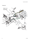
Motor Replacement
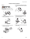
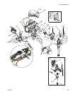
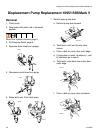
Removal
Relieve pressure; page 9.
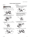
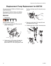
1. Remove pump (91); see Displacement
Pump Replacement, page 34 (695/795)
page 36 (1095/1595/Mark V).
2. Remove drive housing (90); see Drive
Housing Replacement, page 30.
3. Remove shroud (58).
4. Remove four screws (38) and control cover
(96).
5. Remove bottom two screws (39) and allow
control panel (68) to hang down freely.
6. Disconnect all three motor connectors from
motor control board (52).
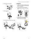
7. Disconnect motor leads.
8. Remove top two screws (39) and control
housing (61).
9. Remove strain relief (29) from motor wires
and power bar plate (69).
10.Remove motor wires from baffle 278075
and remove baffle.
11.Remove two screws (23) and nuts (19) on
side opposite control.
12.Loosen two nuts (19) on side near control
and remove motor (84) from cart frame
(62).
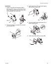
Installation
1. Slide new motor (84) under two screws (23)
in cart frame (62) near control.
2. Install two screws (23) and nuts (19) on
motor side opposite control.
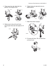
3. Install baffle and connect motor wires.
4. Tighten all four screws (23) and nuts (19).
torque nuts to 115-135 in-lb (13-15 N•m).
5. Install strain relief (29) onto motor wires
and into power bar plate (69).
6. Install control housing (61) with top two
screws (39).
7. Connect motor leads.
8. Connect all three motor connectors to
motor control board (52).
9. Install control panel (68) with two screws
(39).
10.Install control cover (96) with four screws
(38).
11.Install drive housing (90); see Drive
Housing Replacement, page 30.
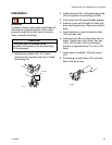
12.Install pump (91); see Displacement
Pump Replacement, page 34 (695/795)
page 36 (1095/1595/Mark V).
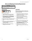
CAUTION
Do not drop gear cluster (89) when removing
drive housing (90). Gear cluster may stay
engaged in motor front end bell or drive
housing.